D
ESCRIPTION
2-3
FUNCTIONAL DESCRIPTION
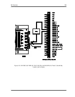
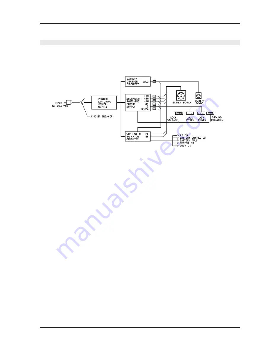
A functional block diagram of the SE 3718S Uninterruptable Power Module is shown in Figure
2-3. The SE 3718S circuitry consists of four main functional elements as described below.
Figure 2-3: SE 3718S Functional Block Diagram
P
RIMARY
S
WITCHING
P
OWER
S
UPPLY
C
IRCUITRY
The purpose of the primary switching power supply circuitry is to convert the input AC (85 to 264
VAC) to a DC level comparable to that provided by an optional backup battery. Normally, this
DC level (not directly available to the end-user) is used to drive the rest of the power supply. In
case of a power failure, this circuitry ceases to operate, and the optional backup battery (if it is
installed) takes over.
There are no user-serviceable parts or fuses associated with the primary switching power supply.
B
ATTERY
C
HARGER
C
IRCUITRY
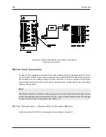
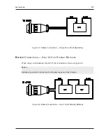
The battery charger circuit has two basic functions. In normal operation, it takes power from the
primary switching power supply and provides a controlled charging current to the optional backup
battery. During power failures, the battery charger circuitry connects the battery to the rest of
the power supply.
To accomplish these functions, the battery charger is equipped with special circuitry to detect the
presence of a viable backup battery, and to monitor its charging state during normal operation.
In the event of a power failure, the circuit is also designed to protect the battery from over-
discharging.
The battery fuse is a 10-amp, metric, slow-blow fuse (5X20 mm 10A T/SB).


