IIISTAIIUIIEOUS
-
n�:��
R
����
U
��g
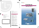
RED DOT
WITH RELATIH INSTANTANEOUS
POLARITY AS SHOWN, THE
DIRECTIOIIAL UIIIT COIIT.I.CTS ClOSE
�VARISTOR
SATURATIMG
TRAIISFOR14ER
IMOUCTIOII DISC
UMIT
DIRECTIONAL UNIT
(LOWER CYL.UNIT)
CIU.SSIS OPERATED
SHORTING SWITCH
RED HANDLE
TEST SWITCH
CURRENT TEST .JACK
TERMINAL
185A421
Fig. 3. Internal Schematic of the Type IRV Relay in the
Type FT31 Case.
Instantaneous Overcurrent Unit (I)
Range
Taps
0 . 5- 2
Amps
0 . 5
0 . 7 5
1 . 0
1 . 25
1 . 5
2
1-4
1 . 0
1 . 5
2.0
2 . 5
3. 0
4 . 0
2-8
2
3
4
5
6
8
4
-
16
4
6
8
9
1 2
1
6
10-40
10
15
20
24
30
40
20-80
20
30
40
48
60
80
Time Overcurrent Unit
Range
Taps
. 5- 2 . 5 0 . 5
0
.
6
0 . 8
1 .0
1 . 5
2 . 0
2 . 5
2-6
2
2 . 5
3
3. 5
4
5
6
4- 1 2 4
5
6
7
8
10
1 2
The tap value is the minimum current required to
just close the relay contacts.
The time vs. current characteristics for the time
overcurrent unit are shown in Figs.
4
to
10.
These
characteristics give the contact closing time for the
various time dial settings when the indicated multi
ples of tap value current are applied to the relay.
The time vs. current characteristics for the in
stantaneous overcurrent unit is shown in Fig.
1 1.
The time vs. current characteristic:; for the
directional unit is shown in Fig.
12.
4
Trip Circuit
The relay contacts will safely close
30
amperes
at
250
volts d.c. and the seal-in contacts of the indi
cating contactor switches will safely carry this cur
rent long enough to trip a circuit breaker.
The indicating contactor switch has two taps
that provide a pickup setting of
0.
2
or
2
amperes. To
change taps requires connecting the lead located in
front of the tap block to the desired setting by means
of a screw connection.
Cylinder Unit Contacts
The moving contact assembly has been factory
adjusted for low contact bounce performance and
should not be changed.
The set screw in each stationary contact has
been shop adjusted for optimum follow and this ad
justment should not be disturbed.
Trip Circuit Constants
Indicating Contactor Switch -
0.2 ampere tap-
6 . 5
ohms d-e resistance
2.0
ampere tap -
0. 1 5
ohms d-e resistance
Auxiliary Switch (CS-1)
The auxiliary switch op erating time
is
approxi
mate l y
5
mil l iseconds.
48-250
volt
d-e
relay
d-e
resistance
-
1165
ohms
24
vol t
d-e
rel ay
d-e
resistance
-
110
ohms (note that series re
sistor is
a
fixed 100
ohm resistor).
Directional Unit
The IRV relay is intended for phase fault pro
tection and the directional unit has its maximum
torque when the current leads the voltage by approx
imately
30
°.
The directional unit minimum pickup is
1.2 volts and
4
amperes at its maximum torque angle
for the
4
to
1 2
ampere range relays and 1.2 volts and
2
amperes for the
0 . 5
to
2.5
ampere and the
2
to
6
ampere range relays.
The directional unit should be connected using
the current in one-phase wire and the potential across
the other two phase wires. This connection is com
monly referred to as the
90
•connection. When utilizing
the
90
•
connection the maximum torque of the relay
occurs when the fault current lags its
100%
P.F.
position by approximately
60
•.
See Fig.
15.
www
. ElectricalPartManuals
. com