background image

EcoDesign Disclosures

1. EU EcoDesign Disclosures

1.4 Chassis Disassembly

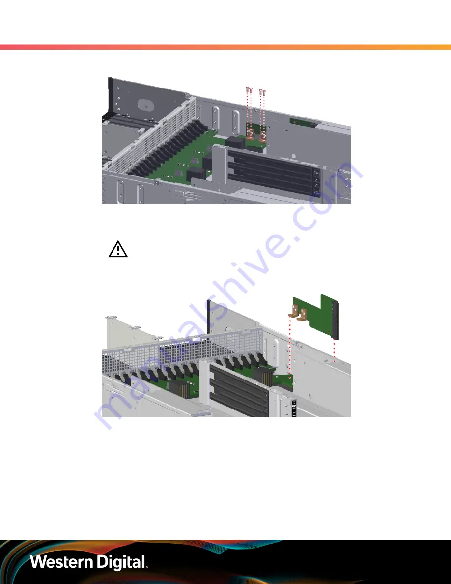
Figure 38: 

PDB-A Screw Locations

c.

Carefully pull PDB-A upward to separate it from its connector on the midplane and remove it

from the Chassis:

Caution: 

To prevent damage to the PDB leads and midplane connector, do

not twist or torque the PDB when removing it from the midplane.

Figure 39: 

PDB-A Removal

Step 17 :

Remove the bottom drive guide plate.

a.

Using a T7 Torx screwdriver, remove the eighteen (18) screws holding the bottom drive

guide plate to the Chassis. There are 9 screws inside each drive bay, and their locations

mirror each other. The left-side screws are shown in the following image:

22

Summary of Contents for DCS0010

Page 1: ...EcoDesign Disclosures OpenFlex Data24 Regulatory Model DCS0010 1ET2362 Version 1 0 December 2020 ...

Page 2: ...s Table of Contents Revision History ii Notices iii Chapter 1 EU EcoDesign Disclosures 1 EcoDesign Overview 2 OpenFlex Data24 EcoDesign Specifications 2 Secure Erasing a Storage Device 2 Chassis Disassembly 3 IO Module IOM Disassembly 27 i ...

Page 3: ...EcoDesign Disclosures Revision History Revision History Date Revision Comment November 2020 1 0 Initial release ii ...

Page 4: ...document or any product referred to herein also expressly agrees Western Digital shall not be liable for any incidental punitive indirect special or consequential damages including without limitation physical injury or death property damage lost data loss of profits or costs of procurement of substitute goods technology or services arising out of or related to this document any related materials o...

Page 5: ...mation and instructions related to the OpenFlex Data24 s disclosures for the EU s ecodesign requirements In This Chapter EcoDesign Overview 2 OpenFlex Data24 EcoDesign Specifications 2 Secure Erasing a Storage Device 2 Chassis Disassembly 3 IO Module IOM Disassembly 27 1 ...

Page 6: ...lt Content in Batteries N A 1 3 Secure Erasing a Storage Device This task provides instructions for performing a Secure Erase on an OpenFlex Data24 storage device using NVMe CLI Before you begin The Secure Erase feature provides the following options for securely erasing the storage device No Secure Erase initializes the number of storage pools on the device User Data Secure Erase deletes the mapp...

Page 7: ...ed T7 Torx screwdriver T8 Torx screwdriver T10 Torx screwdriver Tweezers or needle nose pliers recommended 2 for removal of the Chassis from the rack 1 for the disassembly of the Chassis Step 1 Follow the instructions for removing the enclosure from the rack see the Chassis Disassembly section of the OpenFlex Data24 User Guide Step 2 Place the OpenFlex Data24 on an ESD safe work surface and ensure...

Page 8: ...Figure 2 Drive Assembly Removal c Repeat these steps to remove the remaining Drive Assemblies Step 4 Uninstall the Power Supply Units PSUs a At the rear of the enclosure grasp the ring handle of a Power Supply Unit PSU with your index finger and use your thumb to press the latch release with a pinching motion Figure 3 Power Supply Unit PSU Release Latch Operation b Pull the Power Supply Unit PSU o...

Page 9: ...ing Power Supply Unit PSU Step 5 Uninstall the IO Modules IOMs a Unlock an IO Module IOM by turning its thumbscrew counterclockwise until the threads are disengaged The location of the thumbscrew is shown in the following image Figure 5 IO Module IOM Thumbscrew Operation b Pull the release handle down until the IO Module IOM is unseated from its slot 5 ...

Page 10: ...se Handle Operation c Use the handle to pull the IO Module IOM out of the enclosure Figure 7 IO Module IOM Removal d Repeat these steps to remove the remaining IO Module IOM Step 6 Remove the rear chassis cover a Using a T7 Torx screwdriver remove the sixteen 16 screws securing the rear chassis cover 6 ...

Page 11: ...ar Chassis Cover Screw Locations b Remove the rear chassis cover by lifting it from the back and sliding it toward the rear of the Chassis Figure 9 Removing the Rear Chassis Cover Step 7 Remove the fan cover a Using a T7 Torx screwdriver remove the two 2 screws securing the fan cover 7 ...

Page 12: ...EU EcoDesign Disclosures 1 4 Chassis Disassembly Figure 10 Fan Cover Screw Locations b Remove the fan cover by pressing inward on the latches and lifting the cover away from the Chassis Figure 11 Fan Cover Latches Operation 8 ...

Page 13: ...ver Removal Step 8 Remove the fan backflow guard a Using a T8 Torx screwdriver remove the six 6 screws securing the fan backflow guard Figure 13 Fan Backflow Guard Screw Locations b The fan backflow guard is a single piece of flexible material remove it by lifting it away from the Chassis 9 ...

Page 14: ...Remove the System Fan modules a Each System Fan module has a rounded notch and a rectangular notch with a retaining clip Place your thumb and index finger into the notches squeeze to release the tension clip and pull upward on the System Fan module to remove it from the Chassis Figure 15 System Fan Latch Operation 10 ...

Page 15: ...at these steps to remove the remaining System Fan modules Step 10 Remove the Rack Ears and front system LED PCBA a Using a T10 Torx screwdriver remove the three 3 screws holding each cover to its rack ear 6 screws total Figure 17 Rack Ear Cover Screw Locations b Pull each cover away from its rack ear to remove it 11 ...

Page 16: ...he left rack ear has a system LED PCBA mounted to it Using a T7 Torx screwdriver remove the two 2 screws holding the PCBA to the rack ear Figure 19 Front System LED PCBA Screw Locations d On the PCBA open the connector and separate the LED cable from the PCBA Remove the PCBA and leave the LED cable in place 12 ...

Page 17: ...Figure 20 Front System LED PCBA Removal e Using a T7 Torx screwdriver remove the four 4 screws securing each rack ear to the Chassis 8 screws total The screws are accessed from inside the left and right drive bays Figure 21 Rack Ear Screw Locations f Remove each rack ear 13 ...

Page 18: ...gure 22 Rack Ear Removal Step 11 Remove the top cover assembly a Using a T7 Torx screwdriver remove the fourteen 14 screws holding the top cover assembly to the Chassis Figure 23 Top Cover Assembly Screw Locations b Lift the top cover assembly to remove it from the Chassis 14 ...

Page 19: ...a The rear system LED PCBA is located behind an access panel on the center divider of the IO Module IOM compartment Using a T7 Torx screwdriver remove the three 3 screws holding the panel to the Chassis Figure 25 Rear LED Access Panel Screw Locations b Pull the bottom of the panel outward and then pull the panel down to remove it from the Chassis 15 ...

Page 20: ... Access Panel Removal c Using a T7 Torx screwdriver remove the two 2 screws holding the rear system LED PCBA to the Chassis Figure 27 Rear System LED PCBA Screw Locations d On the PCBA open the connector and separate the LED cable from the PCBA Remove the PCBA and leave the cable in place 16 ...

Page 21: ... the fan bracket and IOM bulkhead will allow access to the midplane and PDBs a Using a T7 Torx screwdriver remove the eight 8 screws from midway along both sides of the Chassis and remove the eight 8 screws from the inside bottom of the fan bracket 16 screws total Figure 29 Fan Bracket Screw Locations b Lift the fan bracket to remove it from the Chassis 17 ...

Page 22: ... Fan Bracket Removal Step 14 Remove the IOM bulkhead a Using a T7 Torx screwdriver remove the two 2 screws from inside the bay for IO Module IOM B Figure 31 IOM B Bulkhead Screw Locations b Using a T7 Torx screwdriver remove the two 2 screws from inside the bay for IO Module IOM A 18 ...

Page 23: ...y Figure 32 IOM A Bulkhead Screw Locations c Lift the IOM bulkhead to remove it from the Chassis Figure 33 IOM Bulkhead Removal Step 15 Remove power distribution board PDB B a Using a T7 Torx screwdriver remove the three 3 screws from inside the bay for IO Module IOM B 19 ...

Page 24: ...er remove the four 4 screws holding PDB B to the midplane Figure 35 PDB B Screw Locations c Carefully pull PDB B upward to separate it from its connector on the midplane and remove it from the Chassis Caution To prevent damage to the PDB leads and midplane connector do not twist or torque the PDB when removing it from the midplane 20 ...

Page 25: ...ribution board PDB A a Using a T10 Torx screwdriver remove the two 2 screws holding PDB A to the side of the Chassis The screws are accessed through holes in the side panel of the bay for IO Module IOM A Figure 37 PDB A Screw Locations b Using a T10 Torx screwdriver remove the four 4 screws holding PDB A to the midplane 21 ...

Page 26: ...ent damage to the PDB leads and midplane connector do not twist or torque the PDB when removing it from the midplane Figure 39 PDB A Removal Step 17 Remove the bottom drive guide plate a Using a T7 Torx screwdriver remove the eighteen 18 screws holding the bottom drive guide plate to the Chassis There are 9 screws inside each drive bay and their locations mirror each other The left side screws are...

Page 27: ...e Screw Locations b Using a T7 Torx screwdriver remove the six 6 screws from underneath the front lip of the drive guide plate Figure 41 Drive Guide Plate Bottom Screw Locations c Pull the bottom drive guide plate forward to remove it from from the Chassis This will expose the two 2 SSD LED PCBAs 23 ...

Page 28: ...mbly Figure 42 Bottom Drive Guide Plate Removal Step 18 Remove the SSD LED PCBAs a On each SSD LED PCBA open the connector and separate the LED cable from the PCBA Figure 43 SSD LED Cable Removal b Using a T10 Torx screwdriver remove the three 3 screws from each PCBA 24 ...

Page 29: ...Disassembly Figure 44 SSD LED PCBA Screw Locations c Lift each PCBA to remove it from the Chassis Figure 45 SSD LED PCBA Removal Step 19 Remove the midplane PCB a Using a T10 Torx screwdriver remove the sixteen 16 screws holding the midplane PCB to the Chassis 25 ...

Page 30: ...it toward the rear of the Chassis This will free the drive connectors from their holes in the mid chassis support Figure 47 Freeing the Drive Connectors c Lift the front edge of the midplane PCB until it is sitting at an upward angle Then remove the midplane PCB The LED cables should slide easily out from the locations where they are threaded into the Chassis 26 ...

Page 31: ...fting the Front Edge Figure 49 Removing the Midplane PCB Result The OpenFlex Data24 Chassis is now disassembled What to do next Proceed to IO Module IOM Disassembly page 27 1 5 IO Module IOM Disassembly This procedure provides instructions for disassembling an OpenFlex Data24 IO Module IOM 27 ...

Page 32: ...uired T7 Torx screwdriver T10 Torx screwdriver 4 5mm nut driver Tweezers or needle nose pliers recommended 1 Step 1 Using a T7 Torx screwdriver remove the eight 8 screws securing the IO Module IOM cannister cover Figure 50 IO Module IOM Cannister Cover Screw Locations Step 2 Slide the cover toward the rear of the IO Module IOM to remove it 28 ...

Page 33: ...ing a T10 Torx screwdriver loosen remove the three 3 screws securing the PCIe support bracket to the IO Module IOM PCB Two of the screws are captive one is not Warning Loosening removing the screws will free the bracket from the IO Module IOM PCB However the connectors will still be attached and could be damaged if not handled safely 29 ...

Page 34: ...52 PCIe Support Bracket Screw Locations Step 4 Carefully pull the bracket upward to separate the connectors between the IO Module IOM riser PCB and IO Module IOM PCB Caution To prevent damage to the connectors do not twist or torque the bracket when removing it from the IO Module IOM 30 ...

Page 35: ...coDesign Disclosures 1 5 IO Module IOM Disassembly Figure 53 PCIe Support Bracket Removal Step 5 Using a T10 Torx screwdriver remove the three 3 screws holding the AICs to the PCIe support bracket Figure 54 AIC Screw Locations 31 ...

Page 36: ...parate its leads from the connector on the IO Module IOM riser PCB Caution To prevent damage to the cards and connectors do not twist or torque the cards when removing them Figure 55 AIC Removal Step 7 Using a T10 Torx screwdriver remove the three 3 screws holding the IO Module IOM riser PCB to the PCIe support bracket 32 ...

Page 37: ...O Module IOM Riser PCB Screw Locations Step 8 Lift the IO Module IOM riser PCB to remove it from the PCIe support bracket Figure 57 IO Module IOM Riser PCB Removal Step 9 Using a T10 Torx screwdriver remove the six 6 screws holding the IO Module IOM PCB to the IO Module IOM cannister base 33 ...

Page 38: ...sassembly Figure 58 IO Module IOM PCB Screw Locations Step 10 Using a 4 5mm nut driver remove the stand off screw near the connectors Figure 59 IO Module IOM Stand Off Screw Location Step 11 Lift the IO Module IOM PCB to remove it from the IO Module IOM cannister base 34 ...

Page 39: ...EcoDesign Disclosures 1 EU EcoDesign Disclosures 1 5 IO Module IOM Disassembly Figure 60 IO Module IOM PCB Removal Result The IO Module IOM is now disassmebled 35 ...

Reviews: