V3.8
OnTime Industrial Ethernet
U/R/T200 series Installation Guide
- 24 -
4.2 FRNT version 1 – multiple rings
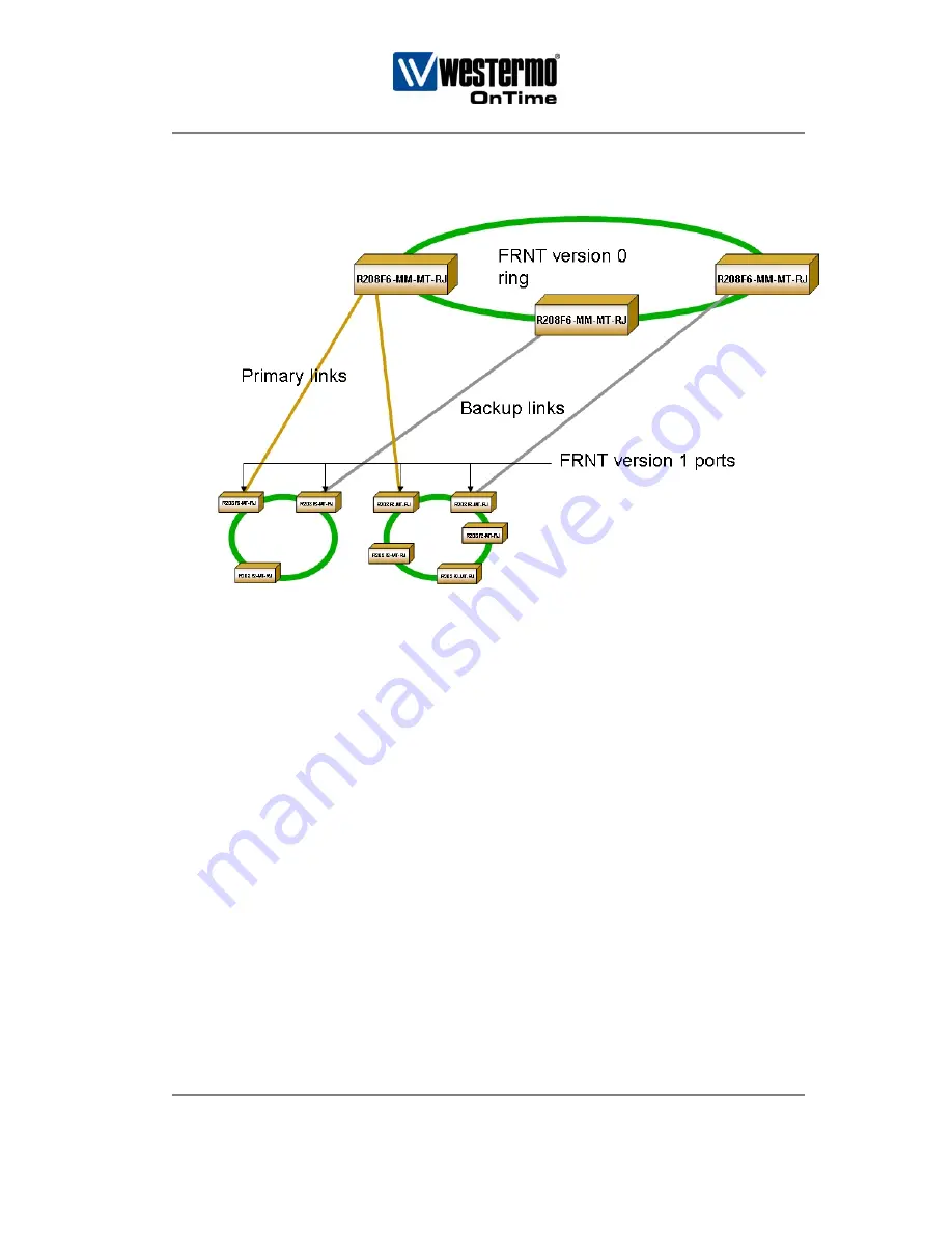
Figure 18, FRNT v1
Connecting two FRNT v0 rings together via redundant bridges creates a configuration called
FRNT v1. One switch acts as the FRNT primary switch and the other as a FRNT secondary
switch. To establish a FRNT v1 configuration follow the steps bellow.
1. Choose one of the switches to be the FRNT primary switch in IP configuration tool.
2. The switch is configured as a FRNT primary switch through the ‘advanced’ dialog box
in the IP configuration tool by ticking the ‘Enable redundant bridge function’ and
‘FRNT primary switch’, see .
3. Define which port that will act as the ‘FRNT enabled port’ in the ‘advanced’ dialog
box. Connect this to the other FRNT v0 ring.
4. Choose one of the switches in the same FRNT v0 ring to be the FRNT secondary
switch in IP configuration tool
5. The switch is configured as a FRNT secondary switch through the advance dialog in
the IP configuration tool by ticking the ‘Enable redundant bridge function’..
6. Define which port that will act as the ‘FRNT enabled port’ in the ‘advanced’ dialog
box. Connect this to the other FRNT v0 ring.


