
31
Cooper Tools GmbH, Carl-Benz-Str. 2, 74354 Besigheim, P.O. Box 1351
Germany, Tel: (07143) 580-0, Fax: (07143) 580108
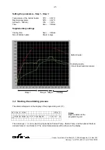
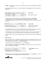
The following functions can be adjusted:
OFFSET NOZ.
: Temperature offset for hot gas temperature
-50°C to +50°C
OFFSET PREH. : Temperature offset for the preheating plate
-50°C to +50°C
STANDBY NOZ. : Standby temperature of the hot air nozzle
OFF to +400°C
STANDBY PREH.: Standby temperature of the preheating plate
OFF to +400°C
FAN SPEED
: Speed setting for the cooling fan
10% to 100%
°C / °F
: Change of the temperature display (from °C to °F)
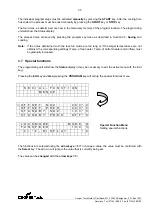
LOOKMODE
: Mode 0
All keys except START, STOP, VAC and DESOLD are blocked
after locking with the
key switch
at the programming unit.
: Mode 1
All keys except START, STOP, VAC and DESOLD are blocked
after locking with the
key switch
at the programming unit.
In addition, programs can be switched but not changed.
Exiting the menu must be confirmed with the
EXIT
key.
Confirm
>
yes
no
4
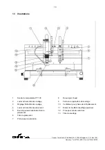
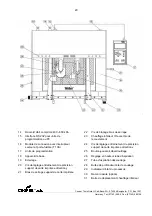
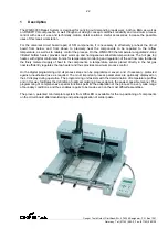
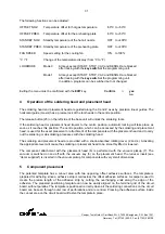
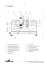
Operation of the soldering head and placement head
The soldering head and placement head are guided along the X and Z axes by precision linear guides. The
horizontal guide (X-axis) has a precise lock of the tool heads in the centre position.
The release button (25) on the left side of the base unit will unlock the soldering tools.
If the soldering head or placement head travels to the centre position, automatic locking will take place as
soon as it reaches this position. The centre position, which can be accessed by the soldering and placement
head, is used for the exact placement or attachment of the components with the placement head and to carry
out the soldering or de-soldering processes with the soldering head.
The soldering and placement head are provided with a shock-absorbed rotating lever (2 and 4). Activating
the appropriate lever will cause the soldering or placement head to be smoothly lifted or lowered.
The component attachment with the placement head (6) is performed with the vacuum pickup (7). The
vacuum is switched on and off with the vacuum key (5) on the placement head. The reducer insert (see
“Items supplied”) is inserted in the vacuum pickup for components with very small dimensions.
5
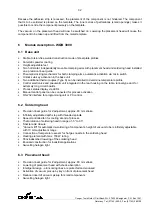
Component placement
The patented template has a cut-out area with two opposing, offset adhesive surfaces. The template is
prepared for adhering since a adhesive strip is laid across the offset adhesive surfaces. A scalpel is used to
create the precise length of the adhesive strip by cutting the overhanging ends along the edge of the
adhesive. The prepared positioning template can now be easily aligned on the terminal grid of the circuit
board, without parallax. The template is positioned correctly when all the soldering connections on the circuit
board can be seen through outer row of perforations and are centred. Pressing the adhesive surface inside
the cut-out area on the circuit board will fasten the template in place.


