background image

24

Cooper Tools GmbH, Carl-Benz-Str. 2, 74354 Besigheim, P.O. Box 1351

Germany, Tel: (07143) 580-0, Fax: (07143) 580108

2.3

Attachment and alignment of the circuit board and soldering nozzle

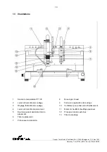
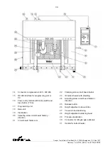
The worktable is equipped with a finely adjustable x-y circuit board holder. The arms of the circuit board
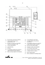
holder (21) can be moved after the clamping screws (22) have been loosened, and the circuit board for
repair can be put in place. Moving both arms in the x-direction and shifting the circuit board on the holder in
the y-direction will roughly align the component that is to be repaired with respect to the nozzle. Both arms
are then fastened in place again with the clamping screws (22). The position of the component to the nozzle
can be checked by lowering the hot gas nozzle (8) and precisely aligned with the x-y fine adjustment (20)
(24).
For an efficient preheating of the circuit board, the bottom heater can be shifted along length of the base
table. Screw in the handle (31) (scope of delivery) in the left or right side of the preheater housing. The
bottom heater can now be aligned to the positioned circuit board.

Depending on the placement of the component, especially in the case of a component that is turned 45°, it
may also be necessary to carry out an alignment along the theta axis. This will require loosening the
clamping screw on the bottom of the soldering head. The lever for the theta adjustment (3) can then be used
to adjust the angle of the hot air nozzle (-5° to 95°). The clamping screw must then be re-tightened.

The depth stop of the soldering head must also be adjusted using the thumb screw (28). When the soldering
head is lowered, the hot gas nozzle may not exert any pressure on the circuit board. If there is not enough
space around the component for the nozzle dimensions, the nozzle can be held above the circuit board at a
specified distance.

When carrying out a de-soldering process, the component is lifted by a vacuum that is integrated in the
nozzle. The thumb screw (26) on the soldering head is used to adjust the height of the vacuum tube (27).
This makes it possible to adjust the position of the vacuum tube to the specific component as well as the
distance of the nozzle to the circuit board.

3

Operation with the programming unit

After the preliminary work is completed, the unit can be switched on at the main switch (16). The name of the
company and the unit and the program version will appear briefly on the LCD display of the programming
unit (17).

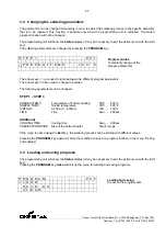
After approx. 4 seconds the display will switch to the Status display. The LED display “Power” am base unit
will illuminate. The unit is now ready for operation.

3.1

Temperature profile

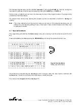
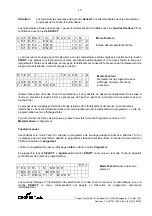
The soldering and de-soldering of BGA or FINEPITCH components is performed according to a temperature
time profile. The temperature profile is composed of four steps.

Preheat zone

(STEP 1)

Soak zone

(STEP 2)

Reflow zone

(STEP 3)

Cooling zone

(COOLING)

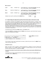
The program locations are given default values in the factory, which are used as a reference for customer-
specific programs (see Section 3.4, Changing the soldering parameters).

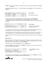
To define a customer-specific temperature profile, the following preliminary settings must be entered at the
programming unit:

Summary of Contents for WQB 3000

Page 1: ...BGA QFP Rework System WQB 3000 Manuel d Utilisation Version 1 4...

Page 2: ...4 Modification des param tres de soudage 3 5 M morisation et chargement de programmes 3 6 D termination de la courbe de temp rature avec des sondes externes Teach In Teach In automatique Teach In man...

Page 3: ...uffage sup rieur gaz chaud r gulation num rique pour la surveillance de la temp rature et r gulation du d bit d air autorise un dosage pr cis de la chaleur sur les composants Une sonde de temp rature...

Page 4: ...essaire au fonctionnement de l appareil La pression d entr e est comprise entre 4 et 6 bars Il est recommand d utiliser une vanne de r gulation externe pour r gler la pression d entr e L air comprim d...

Page 5: ...t e de profondeur de la t te de soudage doit en outre tre r gl e avec la vis molet e 28 Lorsque la t te de soudage est abaiss e la buse gaz chaud ne doit exercer aucune pression sur la carte imprim e...

Page 6: ...auffage inf rieur Small Large Chauffage inf rieur Chauffage sup rieur buse de soudage Carte imprim e sonde externe Step 1 Step 2 Step 3 Cooling 3 2 D marrage du processus de soudage L affichage d tat...

Page 7: ...que la fin de la phase de refroidissement Durant l ex cution de ces phases du programme les temp ratures momentan es des sondes raccord es peuvent tre visualis es en les s lectionnant avec les touches...

Page 8: ...difi s STEP 1 STEP 3 PREHEATTEMP Temp rature du chauffage inf rieur 50 C 400 C NOZZLE TEMP Temp rature de la buse 50 C 400 C AIRFLOW D bit d air 5 50l min 10 100 TIME Temps 0sec 999sec Ainsi que COOLI...

Page 9: ...rentes tapes du programme sont d termin s lorsque des temp ratures cibles pr cises d finies par l utilisateur ont t atteintes Avant le processus de Teach In un programme adapt la t che de soudage doit...

Page 10: ...rrompu tout moment avec la touche Stop Le processus de soudage est termin lorsque le temps de refroidissement est coul Les trois temps d termin s se trouvent maintenant dans la m moire temporaire de l...

Page 11: ...s ou si les temp ratures cibles ne sont pas atteintes augmenter pas pas les valeurs correspondantes temp chauffage sup rieur temp chauffage inf rieur et d bit d air 3 7 Fonctions sp ciales L unit de p...

Page 12: ...de la t te de placement La t te de soudage et la t te de placement se d placent sur des guidages lin aires de pr cision dans l axe X et Z Le guidage horizontal axe X poss de un verrouillage de pr cisi...

Page 13: ...le d acier Rev tement par poudre antistatique Pieds r glables en hauteur 2 bras mobiles ind pendamment dans le plan horizontal avec t te de placement et t te de soudage sur guidage lin aire de pr cisi...

Page 14: ...dage lin aire de pr cision avec 2 chariots pour les bras Entra nement de pr cision en x et y plage de r glage 10 mm pr cision du r glage 0 05 mm Plage de serrage Largeur max 495 mm Largeur min 30 mm L...

Page 15: ...trol pour l utilisation de l appareil avec un PC 8 Accessoires en option Grand choix de buses gaz chaud et de gabarits de positionnement Kit de fixation pour cartes imprim es 587 54 924 Appui pour car...

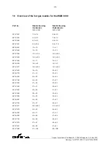
Page 16: ...5 15 5 x 15 5 16 5 x 16 5 587 47 893 15 x 11 16 x 12 587 54 836 18 5 x 10 19 5 x 11 587 47 977 15 5 x 23 5 16 5 x 24 5 587 47 833 18 x 18 20 x 20 587 54 770 21 x 21 23 x 23 587 54 820 22 x 22 24 x 24...

Page 17: ...oucher l outil de soudage et les accessoires Eloignez les autres personnes de l emplacement de travail 6 Conservez votre outil de soudage en un lieu s r Les outils de soudage inutilis s doivent tre ra...

Page 18: ...ommag s V rifiez si les pi ces mobiles fonctionnent correctement si elles ne se bloquent pas et si des pi ces sont endommag es Toutes les pi ces doivent tre mont es correctement et remplir l ensemble...

Page 19: ...icul t te de soudage 3 R glage th ta t te de soudage 4 Levier articul t te de placement 5 Bouton poussoir aspiration t te de placement 6 T te de placement 7 Pr henseur aspiration 8 Buse gaz chaud 9 Fe...

Page 20: ...de r glage entra nement de pr cision support de carte imprim e direction y 21 Bras de serrage support de carte imprim e 22 Vis de blocage bras de serrage 23 Chauffage inf rieur IR avec t le de recouvr...

Page 21: ...3 Program sequence 3 4 Changing the soldering parameters 3 5 Loading and saving programs 3 6 Determining the temperature profile with external Sensors Teach In Automatic Teach In Manual Teach In 3 7...

Page 22: ...rol electronics for temperature monitoring and regulation of the air flow rate facilitates the finely metered supply of heat to the components A temperature sensor placed directly in the hot gas nozzl...

Page 23: ...ssed air supply is required for operation of the unit The supply pressure range is 4 6 bar The use of an upstream pressure control valve is recommended for setting the supply pressure The compressed a...

Page 24: ...e re tightened The depth stop of the soldering head must also be adjusted using the thumb screw 28 When the soldering head is lowered the hot gas nozzle may not exert any pressure on the circuit board...

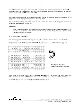
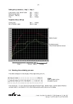
Page 25: ...9sec Size of bottom heater Small Large Bottom heater Soldering nozzle Circuit board external sensor Step 1 Step 2 Step 3 Cooling 3 2 Starting the soldering process The status will appear on the displa...

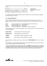
Page 26: ...ds with acoustic signal As these program steps run the current temperatures of the connected sensors can be shown by selecting with the arrow keys NOZZLE TEMP Actual temperature of the top heater nozz...

Page 27: ...e the values The following parameters can be changed STEP 1 STEP 3 PREHEATTEMP Temperature of bottom heating 50 C 400 C NOZZLE TEMP Nozzle temperature 50 C 400 C AIRFLOW Air flow 5 50l min 10 100 TIME...

Page 28: ...emperatures have been reached the process times of the individual program steps will be determined Prior to the Teach In process a program that corresponds to the soldering task must be selected or cr...

Page 29: ...op key The soldering process is concluded after the cooling time sequence The three times as determined are now in the temporary memory of the program location The programming unit shows the Status di...

Page 30: ...not obtained the corresponding settings Temp of top heater Temp of bottom heater and Airflow must be gradually increased 3 7 Special functions The programming unit will show the Status display it may...

Page 31: ...g will take place as soon as it reaches this position The centre position which can be accessed by the soldering and placement head is used for the exact placement or attachment of the components with...

Page 32: ...ofile Control electronics and pneumatic unit integrated in the rear housing on the table tunnel type duct for extremely long circuit boards Process status display via LED s Manual control panel can be...

Page 33: ...ion adjustment range 10 mm accuracy 0 05 mm Adjustment range Width max 495 mm Width min 30 mm Length unlimited 6 6 Programming unit LCD display with background lighting Key switch Connection to the ba...

Page 34: ...oftware WQB 3000 Control for use of the system with PC 8 Accessories optional Large range of different hot gas nozzles and positioning templates Clamping set for circuit boards 587 54 924 Support for...

Page 35: ...587 47 935 15 5 x 15 5 16 5 x 16 5 587 47 893 15 x 11 16 x 12 587 54 836 18 5 x 10 19 5 x 11 587 47 977 15 5 x 23 5 16 5 x 24 5 587 47 833 18 x 18 20 x 20 587 54 770 21 x 21 23 x 23 587 54 820 22 x 22...

Page 36: ...rsons to touch the soldering tool and accessories Keep other persons away from your workstation 6 Store the soldering tool carefully Unused soldering tools should be stored in a dry enclosed location...

Page 37: ...d to ensure perfect and proper function before further use Check moving parts for proper function or sticking as well as for damage All parts must be correctly assembled and fulfil all conditions in o...

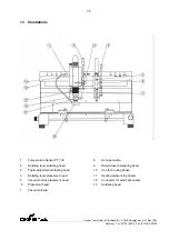
Page 38: ...ure Sensor PT 100 2 Rotating lever soldering head 3 Theta adjustment soldering head 4 Rotating lever placement head 5 Vacuum button placement head 6 Placement head 7 Vacuum pickup 8 Hot gas nozzle 9 R...

Page 39: ...Programming unit 18 Base unit 19 Illumination 20 Adjusting screw circuit board holder y direction 21 Circuit board holder arm 22 Clamping screw circuit board holder 23 IR bottom heater with shielding...

Reviews: