23
Cooper Tools GmbH, Carl-Benz-Str. 2, 74354 Besigheim, P.O. Box 1351
Germany, Tel: (07143) 580-0, Fax: (07143) 580108
Technical data:
Dimensions (l x w x h)
:
approx. 650 X 600X 500 mm
Mains voltage
:
230V, 50/60Hz
Main power supply fuse
:
T10A
Rating
:
2300W
Top heater:
700 W
Bottom heater:
large 1600W (260 X 260)mm
small 400W ( 120 X 120)mm
Compressed air supply
:
400 – 600 kPa purified, dry compressed air
Compressed air converter
:
Low pressure 60kPa
Temperature control
:
50°C – 400°C (continuous)
Control accuracy
±
10°C
Flow rate control
:
5 – 50 l/min (continuous)
Total weight
:
42 kg
2
Start-up
2.1
Set-up
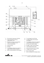
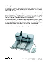
The base unit (18) is equipped with four height-adjustable feet.
The height can be adjusted by turning the feet by hand (no tools required).
The guiding slides for the soldering head and vacuum head are fastened in the outermost positions by a
transport securing device. Screws are found on the left and right of the housing, at the height of the clamping
arms, for securing the unit during transport. These screws must be removed before use.
2.2
Preliminaries and connections
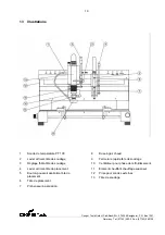
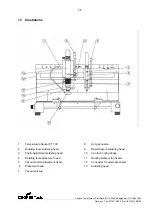
The programming unit for WQB3000 is inserted in the connecting socket (15) and secured in place.
An external compressed air supply is required for operation of the unit. The supply pressure range is 4 - 6
bar. The use of an upstream pressure control valve is recommended for setting the supply pressure. The
compressed air itself must be clean and dry.
A compressed air hose with an external diameter of 6 mm is required for the compressed air connection to
the unit. The hose must be fully inserted into the connecting element (14). Optional the system can be
converted for the use of the top heater with nitrogen gas. Additional to the compressed air connector, the
connector for nitrogen gas (30) must be allocated with a hose with an external diameter of 6 mm.
Ensure that the main switch is turned off.
The connection to the power supply is performed based on the information on the rating plate on the power
entry module (16). Connection is possible only with a specially designed cable, plug or adapter.
The sensor for temperature control is installed on the hot air nozzle for the given component. The
temperature sensor is inserted into the hot air nozzle (at a 45° angle).
The hot air nozzle with temperature sensor is installed on the soldering head (13). The locking lever of the
nozzle fixture (9) is pivoted approx. 90°, and the hot air nozzle is inserted and locked in place again. The
plug for the temperature sensor is inserted into the connecting socket (1) on the soldering head.

