background image

4


z


The ICS 3-304.81 Safety Recommendations are reproduced by permission of the National Electrical 

Manufacturers Association from NEMA ICS 3-304 

2.3 Communications Connections 

The ports as you look at the back of the case, are the ports for connecting to a PLC or some external 

device (Controller Connectors).   

2.3.1 Connector COM1 [RS232], COM2 [RS232] 

Cable 

Requirements 


Caution 

Different cables are required for various devices. Restrict cable length to less than 500’ 

(150m) for RS485/422 devices and 50’ (15m) for RS232 devices to avoid 

communications problems.   
The COM light on the front of the MT-600/8000 will turn on with each Ethernet 

communication. Shielded cable must be used for long lengths or cables run in an 

electrically noisy environment.   
Do not run cables next to AC power lines or near sources of electrical noise. Be sure 

that the cable ends have been inserted all of the way into mating connectors and are 

secure. 
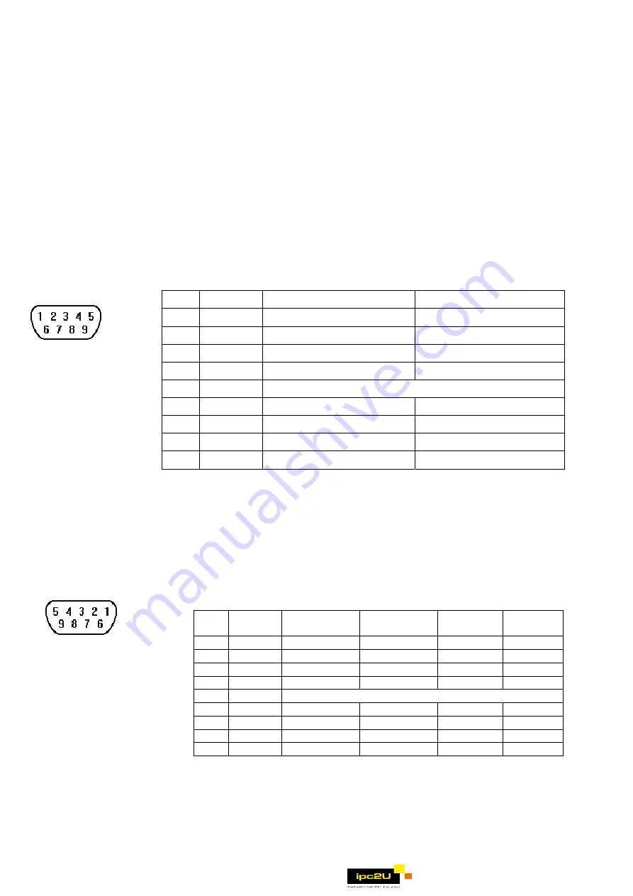
Pin assignment of the 9 Pin, Male, SUB-D, COM1 [RS-232] and COM2 [RS-232] Port. 

Pin Designations 


COM1 [RS-232] 
COM2 [RS-232]


Pin# Symbol 

COM1 [RS232] 

COM2 [RS232] 

1 Not 

used 


2 RxD  Received 

Data 


3 TxD  Transmitted 

Data 


4 TxD   

Transmitted 

Data 

5 GND 

Signal 

Ground 

6 RxD   

Received 

Data 

RTS 

Ready to send output 


CTS 

Clear to send input 


9 Not 

used 


2.3.2 Connector COM1[RS485] , COM3[RS485] and COM3[RS232] 

The 9 Pin, Female, SUB-D, COM1 [RS-485], COM3 [RS-485] and COM3 [RS-232] Port on the back 

of the unit is the RS-232 and RS485/422 communications port for connecting to a controller. 

COM1 [RS485]2w and COM3 [RS485]2w support MPI 187.5K, please select one to use at one time. 

Connection 
Pin Designations 


COM1 [RS-485]


COM3 [RS-485] 

COM3 [RS-232]


Pin assignment of the 9 Pin, Female, SUB-D COM1 [RS-485], COM3 
[RS-485] and COM3 [RS-232] Port 

Pin# Symbol Com1 

[RS485]2w 

Com1 

[RS485]4w 

Com3 

[RS485] 

Com3 

[RS232] 

1 Rx-  Data- 

Rx- 


2 Rx+  Data+ 

Rx+ 


3 Tx- 


Tx- 


4 Tx+   

Tx+ 


5 GND 

Signal 

Ground 

6 Data- 


Data- 


7 TxD   


Transmit

8 RxD   


Receive 

9 Data+ 


Data+ 


2.3.3 USB Host port 

USB 1.1 Host interface supports USB mouse, keyboard, USB Flash Drive and printer.   

While using external hard drive, please use external power supply. Do not use USB port to charge external 

device. 

                         www.ipc2u.ru

Summary of Contents for MT-600 Series

Page 1: ...s not guarantee noise immunity in severe cases Proper wire routing and grounding will insure proper operation Mechanical Environment Avoid installing units in environments where severe mechanical vibration or shocks are present 2 0 Installation Instructions 2 1 Mounting Instructions 2 1 1 Location Considerations Care should be taken when locating equipment behind the unit to ensure that AC power w...

Page 2: ...tions Make sure that all local and national electrical standards are met when installing the unit Contact your local authorities to determine which codes apply 2 2 1 Power Requirements Power The MT 600 8000 can be powered by DC power only The specified voltage range is 24 20 Volts DC This insures compatibility with most controller DC systems The power conditioning circuitry inside the unit is acco...

Page 3: ...guidelines Hardware Considerations WARNING The system designer should be aware that devices in Controller systems could fail and thereby create an unsafe condition Furthermore electrical interference in an operator interface such as an MT 600 8000 can lead to equipment start up which could result in property damage and or physical injury to the equipment operator If you or your company use any pro...

Page 4: ...B D COM1 RS 232 and COM2 RS 232 Port Pin Designations COM1 RS 232 COM2 RS 232 Pin Symbol COM1 RS232 COM2 RS232 1 Not used 2 RxD Received Data 3 TxD Transmitted Data 4 TxD Transmitted Data 5 GND Signal Ground 6 RxD Received Data 7 RTS Ready to send output 8 CTS Clear to send input 9 Not used 2 3 2 Connector COM1 RS485 COM3 RS485 and COM3 RS232 The 9 Pin Female SUB D COM1 RS 485 COM3 RS 485 and COM3...

Page 5: ...ble mini side plug to HMI and another side plug into PC The PC will display Found New Hardware Wizard dialog Select Install from a list or specific location Advanced 2 Check Include this location in the search and assign the path to install Weintek HMI i Series driver from C EB8000 usbdriver 3 If the USB driver successfully be installed user can check it at Computer Management Device Manager Then ...

Page 6: ... input YES Then click OK The default password is 111111 However other passwords including download upload password and History backup password have to be reset Note When the reset action is taken projects and saved data in the HMI will all be cleared 2 4 Requirements EU directives that apply to the MT 600 8000 Series z EMC Directive 2004 108 EC electromagnetic emissions and immunity z UL508 ISBN 0...

Page 7: ...ve type Touch Accuracy Active Area Length X 2 Width Y 2 I O port COM1 RS 232 RS 485 2W 4W COM2 RS232 COM3 RS 232 RS 485 2W Ethernet port 10 100 Base T Audio YES USB Port 1 USB Host port 1 USB Client port Processor 32bit RISC 400MHz Storage 128MB flash memory DRAM 64MB DDR2 RAM on board SD card slot Support SD SDHC RTC Built in CR2032 3V lithium battery General Specification Input Power 24 20 VDC P...

Page 8: ... holes j USB Host port e Line out k USB Client port f SD CARD SLOT GME8104H0_MT8104iH_Installation_120409 R2mm R0 08 MT8104iH 259mm 10 20 W x 201mm 7 91 H 259mm 10 20 201mm 7 91 286 2mm 11 27 212 8mm 8 38 SD COM1 RS232 COM2 RS232 COM3 RS485 COM3 RS232 COM1 RS485 2 4W RESET FUSE GND 24V DIP SW FUSE5X20 257mm 10 12 199mm 7 83 50mm 1 97 d e j i h g f k a c b www ipc2u ru ...

Reviews: