background image

6


2.3.6 Dip Switch 


¼

SW4 is used for adjusting LCD parameters, please keep it in the manufacturer default position, otherwise 

incorrect screen display may be occurred. 

z


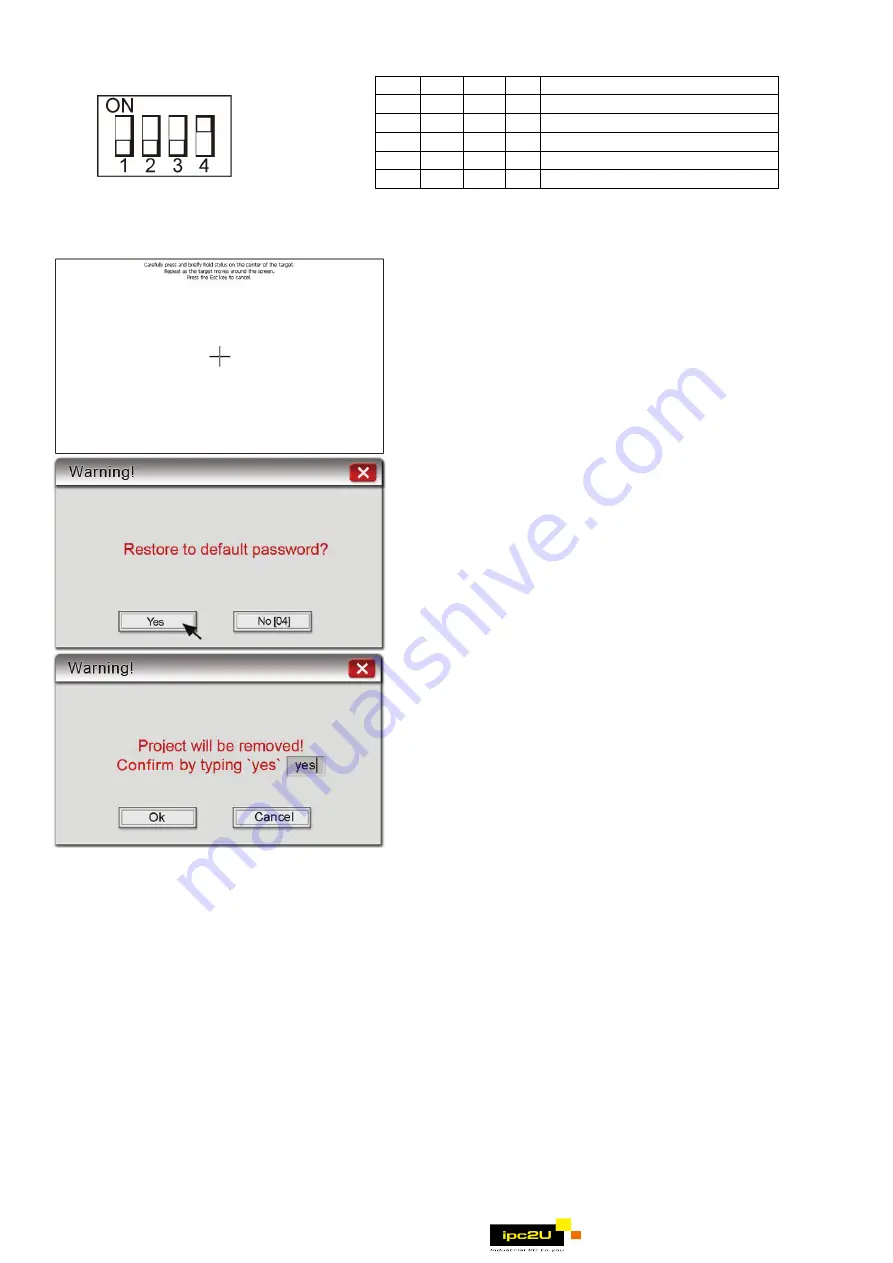
Touch Screen Calibrate and Reset Password mode: 
In this mode when you power on the MT8000 series, 
the screen will display a “+” sign upper-left of the 
screen. Use a stylus or finger to push the center of 
the “+” until it moves. The “+” moves to upper-left, 
upper-right, lower -left, lower-right and center. 
When all five “+” are done the “+” will disappear. 
The Touch Screen parameter will be stored in Flash 
Rom.  

z


If losing or forgetting system passwords, users can 

set Dip Switch 1 and 4 to “ON” position, the rest of 
Dips remain on “OFF” position and then reboot 
MT8000 series. Under this situation, MT8000 series 
will jump to Touch Adjust (Touch screen calibration) 
mode. After calibration, the pop-up window appears 
as the illustration below. Users will be inquired if 
restoring the system password to the default value. 

z


When “YES” is chosen, another pop-up dialog 
appears as below. Users will be confirmed again if 
restoring the system password to the default value 
and will be asked to input “YES”. Then click OK. 
(The default password is 111111. However, other 
passwords, including download, upload password 
and History backup password, have to be reset.) 

Note: When the reset action is taken, projects and saved data 
in the HMI will all be cleared. 


2.4 Requirements 

EU directives that apply to the MT-600/8000 Series: 

z


EMC Directive (2004/108/EC) electromagnetic emissions and immunity. 

z


UL508

ISBN 0-7629-0404-6

machine safety for use in Pollution Degree 2 Environment. 

z


MT600/8000 products will be CE-marked to indicate compliance with the EMC Directive.   


The MT-600/8000 Series has been designed to operate satisfactorily in electromagnetic noise (immunity) and 

without emitting high levels of electrical noise into the environment (emission). The units are designed to 

meet European Community standards when installed per the wiring instructions in this manual. 

Compatibility  

Standards


The MT-600/8000 has been designed to meet electromagnetic compatibility for 

industrial environments. The CE requirements: 

• EN55022:2006+A1:2007, Class A 

• EN61000-3-2: 2006 

• EN61000-3-3:1995+A1:2001+A2:2005 

• EN55024:1998+A1:2001+A2:2003 

SW1 SW2 SW3 SW4 Mode 

ON 

OFF OFF ON Touch Screen Calibrate mode 

OFF ON OFF ON Hide MT8000 System Setting Bar
OFF OFF ON  ON Boot Loader mode 
OFF OFF OFF ON Normal

¼


OFF OFF OFF OFF Not Supported 

                         www.ipc2u.ru

Summary of Contents for MT-600 Series

Page 1: ...s not guarantee noise immunity in severe cases Proper wire routing and grounding will insure proper operation Mechanical Environment Avoid installing units in environments where severe mechanical vibration or shocks are present 2 0 Installation Instructions 2 1 Mounting Instructions 2 1 1 Location Considerations Care should be taken when locating equipment behind the unit to ensure that AC power w...

Page 2: ...tions Make sure that all local and national electrical standards are met when installing the unit Contact your local authorities to determine which codes apply 2 2 1 Power Requirements Power The MT 600 8000 can be powered by DC power only The specified voltage range is 24 20 Volts DC This insures compatibility with most controller DC systems The power conditioning circuitry inside the unit is acco...

Page 3: ...guidelines Hardware Considerations WARNING The system designer should be aware that devices in Controller systems could fail and thereby create an unsafe condition Furthermore electrical interference in an operator interface such as an MT 600 8000 can lead to equipment start up which could result in property damage and or physical injury to the equipment operator If you or your company use any pro...

Page 4: ...B D COM1 RS 232 and COM2 RS 232 Port Pin Designations COM1 RS 232 COM2 RS 232 Pin Symbol COM1 RS232 COM2 RS232 1 Not used 2 RxD Received Data 3 TxD Transmitted Data 4 TxD Transmitted Data 5 GND Signal Ground 6 RxD Received Data 7 RTS Ready to send output 8 CTS Clear to send input 9 Not used 2 3 2 Connector COM1 RS485 COM3 RS485 and COM3 RS232 The 9 Pin Female SUB D COM1 RS 485 COM3 RS 485 and COM3...

Page 5: ...ble mini side plug to HMI and another side plug into PC The PC will display Found New Hardware Wizard dialog Select Install from a list or specific location Advanced 2 Check Include this location in the search and assign the path to install Weintek HMI i Series driver from C EB8000 usbdriver 3 If the USB driver successfully be installed user can check it at Computer Management Device Manager Then ...

Page 6: ... input YES Then click OK The default password is 111111 However other passwords including download upload password and History backup password have to be reset Note When the reset action is taken projects and saved data in the HMI will all be cleared 2 4 Requirements EU directives that apply to the MT 600 8000 Series z EMC Directive 2004 108 EC electromagnetic emissions and immunity z UL508 ISBN 0...

Page 7: ...ve type Touch Accuracy Active Area Length X 2 Width Y 2 I O port COM1 RS 232 RS 485 2W 4W COM2 RS232 COM3 RS 232 RS 485 2W Ethernet port 10 100 Base T Audio YES USB Port 1 USB Host port 1 USB Client port Processor 32bit RISC 400MHz Storage 128MB flash memory DRAM 64MB DDR2 RAM on board SD card slot Support SD SDHC RTC Built in CR2032 3V lithium battery General Specification Input Power 24 20 VDC P...

Page 8: ... holes j USB Host port e Line out k USB Client port f SD CARD SLOT GME8104H0_MT8104iH_Installation_120409 R2mm R0 08 MT8104iH 259mm 10 20 W x 201mm 7 91 H 259mm 10 20 201mm 7 91 286 2mm 11 27 212 8mm 8 38 SD COM1 RS232 COM2 RS232 COM3 RS485 COM3 RS232 COM1 RS485 2 4W RESET FUSE GND 24V DIP SW FUSE5X20 257mm 10 12 199mm 7 83 50mm 1 97 d e j i h g f k a c b www ipc2u ru ...

Reviews: