Part number 550-141-402/0801
8
CER Series 2 Electric-Hydronic Boilers Installation Instructions
Troubleshooting
Symptom—No heat
1.
Check fuses. Power for the control circuit is supplied through the fuses
for the heating element, and the circulator.
2.
If fuses are good, jumper the thermostat terminal. If boiler starts, check
the thermostat and associated wiring.
3.
If thermostat and wiring are good, check the limit control.
a.
Jumper the “R” and “B” terminals on the “low” side of the control.
If the boiler starts, replace the limit control.
b.
If the boiler does not start in step “a”, momentarily jumper the “R”
and “B” terminals on the “high” side of the control. If the boiler
starts, replace the limit control.
4.
If the limit control is good, check the transformer.
a.
Measure the A.C. voltage on the transformer. If the A.C. voltage is
24 volts ± 15%, the transformer is good.
b.
If the A.C. voltage is low, remove one secondary lead from its load
connection.
1) If the A.C. voltage returns to 24V, the transformer is good.
2) If the A.C. voltage remains low, check the primary voltage. It
should measure 240, 208 or 480 volts A.C. accordingly ± 10%.
If the primary voltage is correct, replace the transformer.
5.
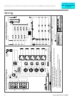
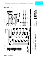
If the transformer is good, follow the voltage path using the wiring
diagram. Check each control for voltage in and out. Replace where
voltage fails.
Symptom—Low heat
One or more contactors do not energize. Operation of any contactor, beyond
the first is dependent upon the operation of three components.
•
Thermal time delay.
•
Electronic time delay; 2½ minutes.
•
Contactor.
1.
Observe the sequence of operation and note at which contactor it is
interrupted. If one contactor fails to energize because of an open coil,
subsequent contactors will be affected (unless one has a shorted coil).
To isolate the trouble, proceed as follows:
a.
Check contactor. Connect a jumper from terminal 3 of the
electronic delay to the transformer wire going to terminal “B” on
the “low” side of the limit control.
b.
If the contactor energizes check electronic and thermal delays.
Remove the jumper from the transformer terminal and touch it
to terminal 1 of the electronic delay. (The jumper now connects
terminals 1 and 3 of the electronic delay). If the contactor
energizes, replace the electronic time delay. If it fails to energize,
replace the thermal time delay.
Symptom—Boiler does not shut
down
One or more contactors remain on after call for heat
ends.
1.
Check contactors. Lower the temperature setting
on “high” side of the limit control to simulate a limit
operation.
a.
If all contactors instantly de-energize, they are
good.
b.
If one or more contactors fail to de-energize,
replace those contactors.
2.
If contactors are good, check the thermal delays.
Return the temperature setting on the “high” side
of the limit control to its original position. Allow
the boiler to sequence on with a normal call for
heat. When all contactors are energized, lower the
setting on the “low” side of the limit control to
satisfy the call for heat. Observe the shutdown
sequence and note the contactor at which it stops.
Remove the wire connecting terminal 1 of the
electronic delay to the thermal delay: The contactor
will now de-energize, and the remaining contactors
will follow in the normal off sequence. Replace the
defective thermal delay.
Symptom—Inoperative
circulator
1.
Measure the voltage at the circulator terminals with
the boiler energized. If the voltage is 120V ± 10%,
the control is good. If no voltage is present, replace
the circulator relay (1K).
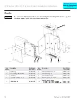
This boiler contains fiberglass materials. Use care when handling these materials per instructions on page 12 of
this manual. Failure to comply could result in severe personal injury.


