background image

Part number 550-141-402/0801

7

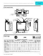
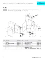
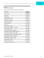
CER Series 2 Electric-Hydronic Boilers Installation Instructions
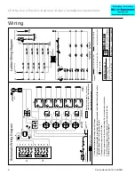
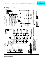
Wiring 

continued

G

OR

RD

(Note 5)

BK

To

FUSES

To

 CIRCULA

TOR

(Note 6)

120 V

AC (for cir

culator)

EQUIPMENT GROUND

SERVICE SWITCH

H

N

WIRE

NUTS

WIRE

NUTS

Schematic

Wir

ing Diag

ra

m

THERMOST

AT

OR END SWITCH

(Note 1)

P

a

rt

 Number

550-224-720/0801

CER

Ser

ies 2

24 KW thr

u 40 KW

208, 240 or 480

V

A

C/3-phase/60 hz

2

½

 min.

ON, 15 sec.

OFF

Legend

HIGH VOL

TAGE FACTOR

Y WIRING

LOW VOLTAGE FACTOR

Y WIRING

HIGH VOL

TAGE FIELD WIRING

LOW VOLTAGE FIELD WIRING

A United Dominion Compan

y

W

eil-McLain 

• 500 Blaine St. 

• Michigan City

, IN 46360-2388

Items not provided

Electrical shock hazard 

 can cause

severe injur

y or death. Disconnect

power before installing or ser

vicing.

1.Thermostat heat anticipator setting must be 0.5 amps.

2.All wiring must be installed in accordance with the requirements of the National Electrical Code and any

applicable national, state or local code requirements.

3.All safety cir

cuit wiring must be N.E.C. Class 1.

4.Use only copper conductors for power input wiring. Do not use aluminum conductors.

5.For 208-volt power supply

, remove orange wire and replace with red wire.

6.Maximum cir

culator motor is 1/6 horsepower

.

1C

2C

4C

TD1

ED1

ED2

ED3

ED4

CONT

ACTORS

THERMAL TIME

DELA

Y RELA

YS

ELECTRONIC

TIME DELA

Y RELA

YS

HEA

TING

ELEMENTS

1K1

1K

TD2

TD3

TD4

H1

H2

H3

H4

2K1

2K

3K

4K

5K

6K

3K1

4K1

5K1

6K1

2K2

3K2

4K2

5K2

6K2

2K3

3K3

4K3

5K3

6K3

1

1

1

3

3

3

3

1

R

B

R

R

R

B

B

B

4

2

3

1

3C

L1

2K1

2K2

2K3

3K1

3K2

3K3

4K1

4K2

4K3

5K1

5K2

5K3

6K1

6K2

6K3

To

:

L2

L3

To

 CIRCULA

TOR

(Note 6)

120 V

AC (for cir

culator)

(208, 240 or 480 V

AC)

SERVICE

SWITCH

H

N

G

THERMOST

A

T

THERMOST

AT

TRANSFORMERTRANSFORMER

TRANSFORMERTRANSFORMER

24 V

A

C

24 V

A

C

HIGH

LIMIT

HIGH

LIMIT

LOW

LIMIT

LOW

LIMIT

THERMAL TIME

DELA

Y RELA

YS

THERMAL TIME

DELA

Y RELA

YS

ELECTRONIC TIME

DELA

Y RELA

YS

ELECTRONIC TIME

DELA

Y RELA

YS

Ladder

Wir

ing Diag

ra

m

EQUIPMENT

GROUND

(Note 1)

F1

F2

F3

F4

F5

2K1

3K1

4K1

5K1

1K

2K

3K

ED1

ED2

ED3

ED4

1C

2C

3C

4C

4K

5K

6K

H1

H2

H3

H4

6K1

2K2

3K2

4K2

5K2

6K2

F6

F7

F8

F9

F10

2K3

3K3

4K3

5K3

6K3

F11

F12

F13

F14

F15

L1

L2

L3

1K1

HIGH

LIMIT

HIGH

LIMIT

LOW

LIMIT

LOW

LIMIT

CIRCULA

TOR RELA

Y

CIRCULA

TOR RELA

Y

HEA

TING

ELEMENTS

Summary of Contents for CER Series 2

Page 1: ...el and the CP number from the boiler jacket You may list the CP number in the space provided on the Installation and service certificate found on page 10 Installer Read all instructions before installing Follow all instructions in proper order to prevent personal injury or death Consider piping and installation when determining boiler location Any claims for damage or shortage in shipment must be ...

Page 2: ...es section failure Addition of oxygen and other gases can cause internal corrosion Leaks in boiler or piping must be repaired at once to prevent makeup water Do not add cold water to hot boiler Thermal shock can cause sections to crack Glycol potential fire hazard All glycol is flammable when exposed to high temperatures If glycol is allowed to accumulate in or around the boiler or any other poten...

Page 3: ...ted temperatures should be avoided The structure to be heated should be insulated in the conventional manner used in your area for electrically heated buildings Boiler must be installed in accordance with these instructions so as not to void our warranty Open the boiler crate and check the contents In the event of shortage or damage notify the transportation company immediately Expansion tank sizi...

Page 4: ...g or servicing The Model CER electric hydronic boilers are pre wired and require only two wires for connection of single phase boilers and three wires for connection of 3 phase boilers Aluminum wire must not be used Add additional 120 volt service must be provided to utilize the circulator control provided in the boiler See wiring diagram on page 6 for single phase or page 7 for 3 phase An opening...

Page 5: ...nds Call for heat satisfied 5 The thermostat contacts open de energizing the first contactor 2K the circulator relay 1K and the heater in the first thermal time delay H1 6 After a minimum of 10 seconds the contacts in the first thermal delay 1C open instantly de energizing the electronic time delay ED1 the second contactor 3K and the second thermal delay heater H2 7 This sequence continues until a...

Page 6: ...tate or local code requirements 3 All safety circuit wiring must be N E C Class 1 4 Use only copper conductors for power input wiring Do not use aluminum conductors 5 For 208 volt power supply remove orange wire and replace with red wire 6 Maximum circulator motor is 1 6 horsepower 1C 2C 4C TD1 ED1 ED2 ED3 ED4 CONTACTORS THERMAL TIME DELAY RELAYS ELECTRONIC TIME DELAY RELAYS HEATING ELEMENTS HEATI...

Page 7: ... Class 1 4 Use only copper conductors for power input wiring Do not use aluminum conductors 5 For 208 volt power supply remove orange wire and replace with red wire 6 Maximum circulator motor is 1 6 horsepower 1C 2C 4C TD1 ED1 ED2 ED3 ED4 CONTACTORS THERMAL TIME DELAY RELAYS ELECTRONIC TIME DELAY RELAYS HEATING ELEMENTS 1K1 1K TD2 TD3 TD4 H1 H2 H3 H4 2K1 2K 3K 4K 5K 6K 3K1 4K1 5K1 6K1 2K2 3K2 4K2 ...

Page 8: ...has a shorted coil To isolate the trouble proceed as follows a Check contactor Connect a jumper from terminal 3 of the electronic delay to the transformer wire going to terminal B on the low side of the limit control b If the contactor energizes check electronic and thermal delays Remove the jumper from the transformer terminal and touch it to terminal 1 of the electronic delay The jumper now conn...

Page 9: ...and automatic air vent if used 2 Fill the boiler and system to an initial pressure of about 12 pounds per square inch 3 Open automatic air vent one turn if used 4 Starting on the lowest floor open air vents one at a time until water squirts out Close vent 5 Repeat with remaining vents 6 Refill to correct pressure Freeze protection when used See WARNING on page 2 for important information regarding...

Page 10: ...Date installed _______________ Measured Btuh input ____________ Installer ________________________ ________________________________ ______________________________ company address phone _____________________________________ installer s signature Installation and service certificate Check limit control operation by lowering the control settings as described in the Troubleshooting section on page 8 R...

Page 11: ... to be lost from relief valve and makeup water added through fill valve Eventual section failure can result If the relief valve opens frequently check the expansion tank If the system has a pressurized tank with a rubber diaphragm separating the air cushion from the water an Ex Trol or equivalent tank use a tire pressure gauge to check the air charging valve on the end of the tank If water flows t...

Page 12: ... dust respirator N95 This type of respirator is based on the OSHA requirements for fiberglass wool at the time this document was written Other types of respirators may be needed depending on the job site conditions Current NIOSH recommendations can be found on the NIOSH web site at http www cdc gov niosh homepage html NIOSH approved respirators manufacturers and phone numbers are also listed on th...

Page 13: ...0 C field wiring Notes 1 and 2 Total amperes Boiler water content Approximate shipping wt KW 208V 240V 480V 208V 240V 480V 208V 240V 480V Gallons lbs Single phase CER 24 82 000 24 3 50 50 1 2 116 101 5 2 170 CER 32 109 000 32 4 50 50 00 0 154 134 5 2 170 C ER 40 137 000 40 5 50 50 000 000 192 167 5 2 170 3 phase CER 24 82 000 24 3 30 30 JKS 15 4 4 8 67 58 29 5 2 170 CER 32 109 000 32 4 30 30 JKS 1...

Page 14: ...n Weil McLain part number Item number Description Weil McLain part number 1 Control tray 428 800 000 6 Jacket element cover plate 428 800 015 2 Boiler casting with insulation 318 806 200 7 Jacket bottom panel 428 600 004 3 Jacket door 428 600 006 8 Jacket bottom cross tie 428 800 010 4 Jacket side and back panel 428 600 008 9 Element opening cover plate 590 243 200 5 Jacket top panel 428 600 002 1...

Page 15: ...t 511 842 362 Relief valve 511 546 924 Temperature pressure gauge 510 218 099 Element contactor 208 240 volt single phase 512 150 148 Element contactor 3 phase 512 050 015 Line terminal and fuse block single phase 512 050 016 Line terminal and fuse block 208 240 volt 3 phase 512 050 017 Line terminal and fuse block 480 volt 3 phase 591 550 229 8KW heating element 208 volt single phase and 3 phase ...

Reviews: