Part number 550-141-402/0801
6
CER Series 2 Electric-Hydronic Boilers Installation Instructions
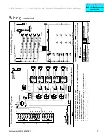
Wiring
G
OR
RD
(Note 5)
BK
To
FUSES
To
CIRCULA
TOR
(Note 6)
To
CIRCULA
TOR
(Note 6)
120 V
AC (for cir
culator)
120 V
AC (for cir
culator)
EQUIPMENT GROUNDEQUIPMENT GROUND
SERVICE SWITCHSERVICE SWITCH
H
N
WIRE
NUTS
WIRE
NUTS
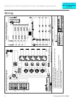
Schematic
Wir
ing Diag
ra
m
THERMOST
A
T
OR END SWITCH
(Note 1)
THERMOST
AT
OR END SWITCH
(Note 1)
P
a
rt
Number
550-224-717/0801
CER
Ser
ies 2
24 KW thr
u 40 KW
208 or 240
V
A
C/single phase/60 hz
2
½
min.
ON, 15 sec.
OFF
Legend
HIGH VOL
TAGE FACTOR
Y WIRING
LOW VOLTAGE FACTOR
Y WIRING
HIGH VOL
TAGE FIELD WIRING
LOW VOLTAGE FIELD WIRING
A United Dominion Compan
y
W
eil-McLain • 500 Blaine St. • Michigan City
, IN 46360-2388
Items not provided
Electrical shock hazard — can cause
severe injur
y or death. Disconnect power
before installing or ser
vicing.
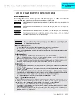
1.Thermostat heat anticipator setting must be 0.6 amps.
2.All wiring must be installed in accordance with the requirements of the National Electrical Code and any
applicable national, state or local code requirements.
3.All safety cir
cuit wiring must be N.E.C. Class 1.
4.Use only copper conductors for power input wiring. Do not use aluminum conductors.
5.For 208-volt power supply
, remove orange wire and replace with red wire.
6.Maximum cir
culator motor is 1/6 horsepower
.
1C
2C
4C
TD1
ED1
ED2
ED3
ED4
CONT
ACTORS
THERMAL TIME
DELA
Y RELA
YS
ELECTRONIC
TIME DELA
Y RELA
YS
HEA
TING
ELEMENTS
HEA
TING
ELEMENTS
1K1
1K
TD2
TD3
TD4
H1
H2
H3
H4
2K1
2K
3K
4K
5K
6K
3K1
4K1
5K1
6K1
2K2
3K2
4K2
5K2
6K2
1
1
1
3
3
3
3
1
R
B
R
R
R
B
B
B
4
2
3
1
3C
L1
2K1
2K2
3K1
3K2
4K1
4K2
5K1
5K2
6K1
6K2
To
:
L2
To
CIRCULA
TOR
(Note 6)
To
CIRCULA
TOR
(Note 6)
120 V
A
C (for cir
culator)
(208 or 240 V
AC)
(208 or 240 V
AC)
SERVICE
SWITCH
H
N
G
THERMOST
A
T
THERMOST
AT
24 V
A
C
24 V
A
C
TRANSFORMERTRANSFORMER
TRANSFORMERTRANSFORMER
HIGH
LIMIT
HIGH
LIMIT
LOW
LIMIT
LOW
LIMIT
THERMAL TIME
DELA
Y RELA
YS
THERMAL TIME
DELA
Y RELA
YS
ELECTRONIC TIME
DELA
Y RELA
YS
ELECTRONIC TIME
DELA
Y RELA
YS
Ladder
Wir
ing Diag
ra
m
EQUIPMENT
GROUND
(note 1)(note 1)
F1
F2
F3
F4
F5
2K1
3K1
4K1
5K1
1K
2K
3K
ED1
ED2
ED3
ED4
1C
2C
3C
4C
4K
5K
6K
H1
H2
H3
H4
6K1
2K2
1K1
3K2
4K2
5K2
6K2
F6
F7
F8
F9
F10
L1
L2
HIGH
LIMIT
HIGH
LIMIT
LOW
LIMIT
LOW
LIMIT
CIRCULA
TOR RELA
Y
CIRCULA
TOR RELA
Y


