30 l
Installation, operation and maintenance manual – Squirrel cage motor – M line – Vertical 11371757
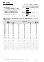
The anchor bolts must be fastened according to Table
4.7
Table 4.7: Tightening torque of the anchor bolts
Type Ø
Dry tightening
torque [Nm]
Tightening torque with
Molycote [Nm]
M30
710
470
M36
1230
820
M42
1970
1300
M48
2960
1950
After positioning the motor, perform the final leveling
using the vertical leveling bolts and the leveling shims.
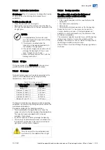
ATTENTION
Protect all the threaded holes to prevent
grout from penetrating the threads during
the grouting of the anchor plate and anchor
bolts.
4.8.5
Natural frequency of the base
In order to ensure a safe operation, the motor must be
precisely aligned with the coupled equipment and both
must be properly balanced.
As a requirement, the motor installation base must be flat
and meet the requirements of DIN 4024-1 standard.
In order to verify if the criteria of the standard are being
met, the following potential vibration excitation
frequencies generated by the motor and coupled
machine must be checked:
The motor rotation frequency;
The double of the rotation frequency;
The double of the motor electric frequency.
According to DIN 4024-1 standard, the natural
frequencies of the base or foundation must be away from
these potential excitation frequencies, as specified next:
The first natural frequency of the base or foundation
(first order natural frequency of the base) must be out
of the range from 0.8 to 1.25 times any of the potential
excitation frequencies above;
The other natural frequencies of the base or foundation
must be out of the range from 0.9 to 1.1 times any of
the potential excitation frequencies above.
4.8.6
Leveling
The motor must rest on a surface with flatness of up to
0.08 mm/m.
Verify whether the motor is perfectly leveled, both in the
vertical and horizontal planes. Make the proper
adjustments by placing shims under the motor. The
motor leveling must be checked with proper equipment.
NOTE
At least 75% of the motor foot support
surfaces must rest on the motor base.
4.8.7
Alignment
The motor must be correctly aligned with the driven
machine.
ATTENTION
Incorrect alignment can damage the
bearings, generate excessive vibration and
even break the shaft.
The alignment must be done according to the coupling
manufacturer recommendations.
The motor and driven machine shafts must be aligned in
the axial and radial directions, as shown in Figure 4.10
and Figure 4.11.
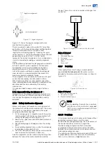
Figure 4.10: Parallel alignment
Figure 4.10 shows the parallel misalignment of the two
shaft ends and the practical way to measure it by using
suitable dial gauges.
The measurement is performed in four points 90° away
from each other with the two half-couplings rotating
together in order to eliminate effects of support surface
irregularities on the dial gauge tip. Choosing the upper
vertical point as 0°, half of the difference between the dial
gauge measurements at the 0° and 180° points
represents the vertical coaxial error. In case of deviation,
it must be corrected by adding or removing leveling
shims. Half of the difference between the dial gauge
measurements at the 90º and 270º points represents the
horizontal coaxial error.
These measurements indicate when it is necessary to lift
or lower the motor, or move it to the right or to the left on
the drive end in order to eliminate the coaxial error.
Half of the maximum difference among the dial gauge
measurements in a complete rotation represents the
maximum eccentricity found.
The misalignment in a complete shaft rotation, with rigid
or semiflexible coupling, cannot exceed 0.03 mm.
When flexible couplings are used, greater values than
those indicated above are acceptable, provided that they
do not exceed the value allowed by the coupling
manufacturer.
It is recommended to keep a safety margin for these
values.
Parallel misalignment
Radial measurement

