26 l
Installation, operation and maintenance manual – Squirrel cage motor – M line – Vertical 11371757
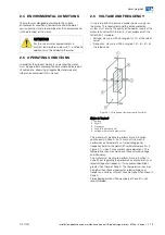
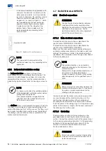
In the case of radiators for applications with
seawater, the materials in contact with the
water (pipes and plates) must be corrosion
resistant. Furthermore, the radiators may be
fitted with sacrificial anodes (e.g., zinc or
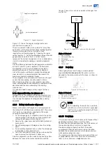
magnesium), as shown in Figure 4.7, which
are corroded during the heat exchanger
operation, protecting the radiator heads.
In order to maintain the integrity of the
radiator heads, these anodes must be
replaced periodically according to their
corrosion level.
Figure 4.7: Radiator with sacrificial anodes
NOTE
The type, quantity and position of the
sacrificial anodes may vary according to the
application.
4.6.2
Independent ventilation cooling
The independent fans are driven by three-phase
asynchronous motors with integral terminal boxes. The
characteristic data (frequency, voltage, etc.) are on the
nameplate of these motors, and the rotation direction is
indicated by a plate affixed to the fan housing or close to
it.
NOTE
It is necessary to check the rotation direction
of the independent ventilation motors before
putting them into operation.
If the rotation direction is opposite to the
specified, invert the connection of two of
their power supply phases.
The air filters (if any), which prevent the ingress of dirt into
the motor, must be regularly inspected according to the
section “Maintenance Plan” of this manual. The filters must
be in perfect condition to ensure the correct operation of
the cooling system and the continuous protection of the
motor sensitive internal parts.
4.7
ELECTRICAL ASPECTS
4.7.1
Electrical connections
ATTENTION
Analyze the electrical connection diagram
supplied with the motor
carefully before
beginning the connection of the main cables
and those of the accessories. For the
electrical connection of auxiliary equipment,
refer to their specific manuals.
4.7.1.1
Main electrical connections
The location of stator terminal box is identified in the
specific motor DIMENSIONAL DRAWING.
The location of stator terminal box is identified in the
specific motor DIMENSIONAL DRAWING.
Make sure the cross section and insulation of the main
connection cables are suitable for the motor current and
voltage. The motor must rotate in the rotation direction
specified on the nameplate and on the sign arrow affixed
to the motor drive end.
NOTE
The rotation direction is, by convention,
determined looking to the shaft end at the
motor drive end.
Motors with a single rotation direction must
only rotate in the indicated direction.
In order to operate the motor in the rotation
direction opposite to the specified, consult
WEG.
ATTENTION
Before making the connections between the
motor and the power supply, it is necessary
to perform a careful measurement of the
winding insulation resistance.
In order to connect the motor main power supply cables,
unscrew the cover of the stator terminal box, cut the
sealing rings (standard motors without cable gland)
according to the diameter of the cables to be used and
insert the cables in the sealing rings. Cut the power supply
cables to the necessary length, strip the ends and mount
the cable lugs that will be used.
4.7.1.2
Grounding
The motor frame and the main terminal box must be
grounded before connecting the motor to the supply
system. Connect the metallic sheath of the cables (if any)
to the common grounding conductor. Cut the grounding
conductor to the proper length and connect it to the
terminal in the terminal box and/or on the frame.
Fasten all connections firmly.
ATTENTION
Do not use washers made of steel or other
materials with low electrical conductivity to
fasten the cable lugs.
Sacrificial anodes

