11371757 Installation, operation and maintenance manual – Squirrel cage motor – M line – Vertical
l 23
The polarization index allows the assessment of the motor
insulation conditions.
DANGER
In order to avoid accidents, the winding must
be grounded immediately after measuring the
insulation resistance.
4.4.6
Conversion of the measured values
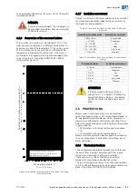
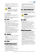
The insulation resistance must be referred at 40°C. If the
measurement is performed at a different temperature, it is
necessary to correct the reading to 40°C by using a curve
of the insulation resistance variation as a function of the
temperature, obtained at the motor itself. If this curve is
not available, the approximate correction provided by the
curve in Figure 4.6, according to NBR 5383 / IEEE43
standard, may be used.
Figure 4.6: Insulation resistance variation coefficient according
to the temperature
4.4.7
Insulation assessment
Table 4.2 and Table 4.3 present guiding limits of insulation
resistance and polarization index for the assessment of
the motor insulation conditions.
Table 4.2: Insulation resistance guiding limits on electrical
machines
Insulation resistance value
Insulation assessment
2 M
Ω
or lower
Unacceptable
< 50 M
Ω
Dangerous
50...100 M
Ω
Fair
100...500 M
Ω
Good
500...1000 M
Ω
Very Good
> 1000 M
Ω
Excellent
Table 4.3: Polarization index (ratio between 10 minutes and 1
minute)
Polarization Index
Insulation assessment
1 or lower
Unacceptable
< 1.5
Dangerous
1.5 to 2.0
Fair
2.0 to 3.0
Good
3.0 to 4.0
Very Good
> 4.0
Excellent
ATTENTION
If the measured insulation resistance,
referred to 40 ºC, is below 100 M
Ω
or the
polarization index is below 2, than before
putting the motor into operation, consult
WEG.
4.5
PROTECTIONS
Motors used in continuous duty must be protected
against overloads by means of a motor integral device, or
an independent protection device, which is generally a
thermal relay with rated or adjustable current equal to or
below the value obtained by multiplying the full load motor
supply current by:
1.25 for motors with service factor equal to or above
1.15;
1.15 for motors with service factor equal to 1.0.
Motors also have protection devices against overheating
(in cases of overloads, locked rotor, low voltage, lack of
motor ventilation).
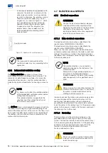
4.5.1
Thermal protections
The over-temperature protections devices are installed on
the main stator, bearings and other parts that require
temperature monitoring and thermal protection.
These sensors must be connected to an external
temperature monitoring and protection system.
The type of temperature sensor, the connection terminals
and the setting temperatures for alarm and shutdown are
given in the motor CONNECTION DIAGRAM.
Winding temperature ºC
R
40ºC
= Rt x Kt
40ºC
To convert the insulation resistance
measured (Rt) for 40 ºC, multiply by the
temperature coefficient (Kt)
C
oe
ffi
ci
en
t
of
in
su
la
tio
n
re
si
st
an
ce
v
ar
ia
tio
n
K
t
40
ºC

