3
CFW-11M RB |3-13
Installation and Connection
1
1
3
3
2
2
A
B
C
D
A’
B´
C´
D´
E
F
F
F
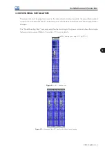
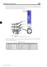
Figure 3.16 -
Symmetry details of the panel constructive layout
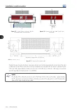
The interconnection between the DC bus and each UP11 can be done with flat braided cables according
to the figure 3.17. The flat braided cables are sized to withstand the DC bus current, presented at table 8.1.
The figure 3.19 presents an example of flat braided cable used by WEG, using a fuse at +UD. Alternatively,
fuses at both connections (+UD and –UD) can be used.
NOTE!
It is important that all the flat braided cables present the same length (defined by the dimension
“E”) that will depend on the panel construction, and that all the fuses mounted on the DC bus are
identical and mounted on the same busbar (+UD or –UD) in all the UP11’s when only one fuse per
UP11 is used (in order to get more details refer to the section 3.4.3).


