3
CFW-11M RB |3-5
Installation and Connection
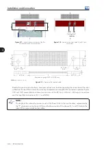
Figure 3.5 -
Fixing holes of the power unit
195
125
25.3
195
97.5
24.9
509.8
100.5
100.5
14.5
14.5
9.2
SUPORTES PARA
FIXAÇÃO SUPERIOR
DO DRIVE
Supports for top
fixing of the
module
14.5 (0.6)
14.5 (0.6)
25
.3 (
1)
24
.9
(1)
50
9.
8 (
20
.1
)
195 (7.7)
195 (7.7)
97.5 (3.8)
125 (4.9)
∅
9.2 (0.4)
100.5 (4) 100.5 (4)
Note:
dimensions in mm (in).
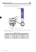
Figure 3.6 -
Supports for top fixing
Mounting of the UC11 at the panel door: Control rack with flange mounting and IPS1 module mounted
inside the panel door. The control rack is secured with four M3 screws (recommended tightening torque:
0.5 N.m).


