


16
MOWING TIPS
• Mower should be properly leveled for best
mowing performance. See “TO LEVEL
MOWER HOUSING” in the Service and
Adjustments section of this manual.
• The left hand side of mower should be
used for trim ming.
• Drive so that clippings are dis charged
onto the area that has already been cut.
Have the cut area to the right of the riding
mower. This will result in a more even
dis tri bu tion of clippings and more uniform
cutting.
• When mowing large areas, start by turning
to the right so that clippings will discharge
away from shrubs, fences, driveways,
etc. After one or two rounds, mow in the
opposite direction making left hand turns
until finished.
• If grass is extremely tall, it should be
mowed twice to reduce load and possible
fire hazard from dried clip pings. Make
first cut relatively high; the second to the
desired height.
• Do not mow grass when it is wet. Wet
grass will plug mower and leave undesir-
able clumps. Allow grass to dry before
mowing.
• Reg
u late ground speed by se lect ing a low
enough gear to give the mower cut ting
per for mance as well as the quality of cut
desired.
• When operating attachments, se lect a
ground speed that will suit the terrain and
give best performance of the at tach ment
being used.
29
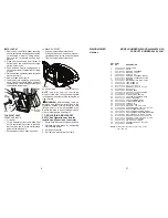
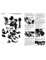
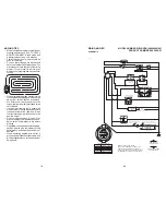
BATTERY
FUSE
D
E
R
RED
RED
WHITE
BLACK
BLUE
BLACK
BLACK
BLACK/WHITE
BLUE
BLACK
BLACK
GRAY
GRAY
BLACK
SOLENOID
M
STARTER
CLUTCH / BRAKE
(PEDAL UP)
SEAT SWITCH
(NOT OCCUPIED)
IGNITION
UNIT
FUEL SHUT-OFF
SOLENOID
S
M
B
G
A1
A2
L
REVERSE SWITCH
SPARK PLUGS
GAP
(2 PLUGS
ON TWIN CYL. ENGINES)
NOT IN REVERSE
SHORTING CONNECTOR
ATTACHMENT CLUTCH
(CLUTCH OFF)
REMOVABLE
CONNECTIONS
WIRING INSULATED CLIPS
NOTE: IF WIRING INSULATED CLIPS
WERE REMOVED FOR SERVICING OF
UNIT, THEY SHOULD BE RE-INSTALLED
TO PROPERLY SECURE YOUR WIRING.
IGNITION SWITCH
CIRCUIT
POSITION
OFF
B+A1
RUN/OVERRIDE
B + S + A1
START
M+G+A1
B+A1
RUN
“MAKE”
L+A2
NON-REMOVABLE
CONNECTIONS
STATOR
DIODE
28 VOLTS AC MIN. @ 3600 RPM
(CHARGING SYSTEM DISCONNECTED)
CHARGING SYSTEM OUTPUT
3 AMP DC @ 3600 RPM
(IF EQUIPPED)
SCH24
RIDING MOWER
MODEL NUMBER WELRVBA (96026000100)
SCHEMATIC
PRODUCT NUMBER 960 26 00-01


