


36
41
16
27
37
38
39
26
23
36
35
34
17
19
19
15
13
9
11
20
10
2
6
7
7
29
6
2
6
7
7
6
5
1
3
2
30
28
4
42
1
3
2
30
43
14
14
32
43
44
31
12
38
38
4
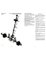
LRV-B_Steering_3
32
RIDING MOWER
MODEL NUMBER WELRVBA (96026000100)
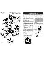
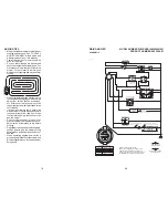
STEERING
PRODUCT NUMBER 960 26 00-01
9
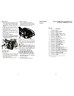
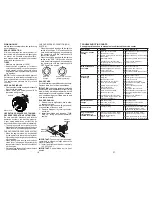
CHECK TIRE PRESSURE
The tires on your riding mower were overin-
flated at the factory for shipping purposes.
Correct tire pressure is important for best
cutting performance.
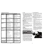
CHECK DECK LEVELNESS
For best cutting results, mower housing
should be properly leveled. See “TO LEVEL
MOWER HOUSING” in the Service and
Adjustments section of this manual.
CHECK FOR PROPER POSITON OF
MOWER DRIVE BELT
See the figure that is shown for replacing the
mower drive belt in the service and adjust-
ment section of this manual. Verify that the
belt is routed correctly.
CHECK BRAKE SYSTEM
After you learn how to operate your riding
mower, check to see that the brake is oper-
ating properly.
✓
CHECKLIST
Before you operate your new riding mower,
we wish to assure that you receive the best
performance and satisfaction from this Qual-
ity Product.
Please review the following checklist:
✓
All assembly instructions have been
com plet ed.
✓
No remaining loose parts in carton.
✓
Battery is properly connected.
✓
Seat is adjusted comfortably and tight-
ened securely.
✓
All tires are properly inflated. (For ship-
ping purposes, the tires were overinflated
at the factory.)
✓
Be sure mower deck is properly leveled
side-to-side/front-to-rear for best cutting
results. (Tires must be properly inflated
for leveling.)
✓
Check mower belt. Be sure it is routed
properly around pulleys and inside all belt
keepers.
✓
Check wiring. See that all connections
are still secure and wires are properly
clamped.
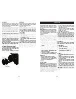
While learning how to use your riding mower,
pay extra attention to the following important
items:
✓
Engine oil is at proper level.
✓
Fuel tank is filled with fresh, clean, regular
unleaded gasoline.
✓
Become familiar with all controls, their
location and function. Operate them
before you start the engine.
✓
Be sure brake system is in safe operating
condition.
✓
Be sure Operator Presence System and
Reverse Operation System (ROS) are
working properly (See the Operation and
Maintenance sections in this manual.)


