Weed Eater 96026000100 Owner'S Manual Download Page 12

12

The op er a tion of any riding mower can  result in foreign objects thrown 

into the eyes, which can result in severe eye dam age.  Al ways wear 

safety glass es or eye shields while op er at ing your riding mower or 

per form ing any ad just ments or repairs.  We rec om mend a wide vi sion 

safe ty mask over spec ta cles or stan dard safety glass es.

00155

HOW TO USE YOUR RIDING 

MOWER

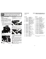
TO SET PARKING BRAKE 

Your riding mower is equipped with an opera-

tor presence sens ing  switch.  When engine 

is running, any attempt by the op er a tor to 

leave the seat without first setting the parking 

brake will shut off the engine.
1.  Depress brake pedal all the way down 

and hold.

2.  Pull parking brake lever up and hold, 

release pressure from brake pedal, then 

release parking brake lever.  Pedal should 

remain in brake position.  Ensure parking 

brake will hold mower secure.
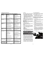
STOPPING 

MOWER BLADE -
•  To stop mower blade, move deck clutch 

lever to disengaged po si tion.

GROUND DRIVE -

•  To stop ground drive, depress brake pedal 

all the way down.

•  Move motion control lever to neutral posi-

tion.

(

Deck Clutch

 Control 

 “Dis 

en gaged”

(

)

 Deck Clutch 

 Control 

 “Engaged”

ENGINE - 

•  Move throttle control between half and full 

speed (fast) position.

NOTE:

  Failure to move throttle control be-

tween half and full speed (fast) position, be-

fore stopping, may cause engine to “backfire”.

•  Turn ignition key to “STOP” position and 

remove key.  Always remove key when 

leaving riding mower to prevent un au tho r-

ized use.

IMPORTANT: 

 Leaving the ignition switch in 

any position other than "STOP" will cause 

the battery to discharge and go dead.

NOTE:

  Under certain conditions when riding 

mower is standing idle with the engine run-

ning, hot engine exhaust gases may cause 

“browning” of grass.  To eliminate this pos-

sibility, always stop engine when stopping 

riding mower on grass areas.

CAUTION:

  Always stop riding mower 

com plete ly, as described above, before 

leav ing the operator's position.

Throttle

Motion Control Lever

33

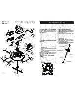
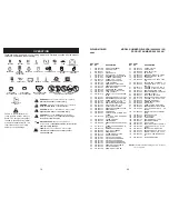
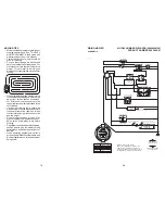
532 43 61-76  WELDMENT, CHASSIS

532 18 01-66  BRACKET, SEAT

532 43 61-77  PLATE, ENGINE

532 43 68-60  BRACKET, CHASSIS FRONT

10 

532 44 18-05  PAN, SEAT

11 

532 19 93-70  BRACKET, SWITCH MOUNTING

13 

532 43 65-95  COVER, FOOT REST

14 

532 43 65-92  STRUCTURE, FOOT REST

15 

532 44 20-69  SUPPORT, FOOT REST

16 

532 43 94-01  PANEL ASM, CONTROL

18 

– – – – – –   ENGINE, 215807-1529-G1 

(439273) (NON-CALIFORNIA) 

(ORDER PARTS FROM 

ENGINE MANUFACTURER) 

19 

532 43 68-61  KEEPER, BELT

22 

532 44 21-30  DECK CLUTCH ASM

23 

532 14 98-46  KNOB

25 

872 14 04-24  BOLT

26 

873 51 04-00  NUT, 1/4-20

29 

532 43 89-21  BOLT, 7/16-20 X 1.00

32 

817 06 06-20  SCREW 3/8-16 X 1-1/4

33 

532 12 41-81  SPRING, SEAT

34 

532 12 37-40  SPRING

35 

872 05 04-12  BOLT, 1/4-20 X 1 1/2

39 

532 13 43-00  SPACER

40 

532 12 12-48  BUSHING, NYLON SNAP

41 

532 12 39-76  NUT, LOCK

42 

532 17 18-52  BOLT, 5/16-18 SHOULDER

43 

873 80 05-00  NUT, 5/16-18

44 

532 43 66-12  SEAT

45 

817 00 05-12  BOLT, 5/16-18 X 3/4

51 

532 42 88-56  BRACKET

52 

532 14 50-06  CLIP PUSH-IN HINGED

53 

532 43 85-62  SCREW

54 

532 43 64-73  DISC FRICTION

55 

532 43 58-08  TORSION BODY UPPER

56 

532 44 19-25  TORQUE ASM CONTROL 

LOWER

57 

532 43 64-79  SPRING HELIX

59 

819 18 24-11  WASHER 9/16ID X1 1/2OD 11G 

ZIN

60 

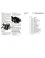
532 43 78-56  FUEL TANK ASM

62 

532 40 04-14  FUEL LINE

63 

532 41 41-19  PURGE LINE

KEY PART

NO. NO. 

DESCRIPTION

KEY PART

NO. NO. 

DESCRIPTION

NOTE:

 All component dimensions given in U.S. inches

         1 inch = 25.4 mm

64 

532 12 34-87  CLAMP HOSE

65 

532 43 85-96  FUEL CAP

66 

532 43 66-06  FUEL TANK SUPPORT BRKT

67 

532 42 17-56  SCREW #10 X 0.500

68 

532 43 98-51  SHIELD HEAT

69 

532 43 74-27  BRACKET MOUNT CABLE

70 

532 44 20-68  CONSOLE CENTER 

CUPHOLDER

71 

532 43 78-57  THROTTLE ASM

72 

532 19 51-61  STUD FASTNER

73 

873 90 05-00  NUT LOCK HEX FLANGE 5/16-

18

76 

877 10 08-12  PIN CLEVIS

77 

876 02 02-08  PIN COTTER 1/16 X 1/2

78 

532 43 70-56  BRACKET SUPPORT ROD

79 

532 43 70-57  BRAKE WELDMENT

80 

532 42 96-93  BRAKE PEDAL COVER

81 

532 43 73-74  WELDMENT LINK CONNECTING

82 

532 16 94-84  RETAINER CLIP

83 

532 43 93-68  STEERING BOOT REAR

84 

532 43 92-91  STEERING BOOT FRONT

85 

532 43 76-60  PARKING BRAKE HANDLE

86 

532 43 87-62  ACTUATOR PARKING BRAKE

87 

532 16 54-92  SHOULDER BOLT

88 

532 42 81-10  CROSS BRACE

91 

532 43 74-01  TRACK CLUTCH BRKT

94 

874 49 05-48  BOLT

95 

532 43 67-02  BRACKET

97 

532 43 64-72  PULLEY ENGINE

98 

817 49 04-08  SCREW 1/4-20 X 1/2

104  818 10 10-08  SCREW #10-14 X 1/2

105  532 44 21-34  ENGINE COVER

106  532 43 68-34  STRAP BATTERY

108  532 43 71-68  COVER REAR TRANSAXLE

109  532 43 90-08  RETAINER BRAKE

110  532 42 21-45  CONTROL HINGE PIN

111  532 43 81-71  SHIELD, BRAKE CABLE

112  817 72 04-08  SCREW THD CUT

RIDING MOWER 

MODEL NUMBER WELRVBA (96026000100)

CHASSIS


PRODUCT NUMBER 960 26 00-01

Summary of Contents for 96026000100

Page 1: ...ervice through its authorized distributors and dealers therefore all requests for parts and service should be directed to your local dealer s The philosophy of HOP is to continually improve all of its...

Page 2: ...Battery must be maintained in accordance with the instructions furnished 4 The Warranty does not apply to any products used for rental or commercial purposes 5 This Warranty applies only to products w...

Page 3: ...e machine only in daylight or good artificial light Do not operate the machine while under the influence of alcohol or drugs Watch for traffic when operating near or crossing roadways Use extra care w...

Page 4: ...the operator Be alert and turn machine off if a child enters the area Beforeandwhilebacking lookbehindand down for small children Never carry children even with the blade shut off They may fall off an...

Page 5: ...hing immediately Never overfill fuel tank Replace gas cap and tighten securely GENERAL SERVICE Never operate machine in a closed area Keep all nuts and bolts tight to be sure the equipment is in safe...

Page 6: ...u experience any problem you cannot easily remedy please contact a qualifiedservicecenter Wehavecompetent well trained representatives and the proper tools to service or repair this riding mower Pleas...

Page 7: ...ong dotted lines on all four panels of carton Remove end panels and lay side panels flat 3 Remove packing materials from riding mower 4 Check for any additional loose parts or cartons and remove NOTE...

Page 8: ...djustment handle Bolt Flat washer Seat pan Pad Tape Slot Tab LUMBAR SUPPORT Loosen lumbar adjustment knob Slide seat back up or down to most com fortable position for lower back support Tighten lumbar...

Page 9: ...h to assure that you receive the best performanceandsatisfactionfromthisQual ity Product Please review the following checklist All assembly instructions have been completed No remaining loose parts in...

Page 10: ...LOCK TENSION CHAIN 33 532 43 61 50 SPRING ADJUSTER TENSION 34 877 10 10 40 PIN CLEVIS 5 16 X 2 1 2 36 532 43 57 22 SHAFT INPUT CLUTCH 37 532 43 61 52 SPROCKETSPLINED14TOOTH 39 532 43 04 70 BEARING BAL...

Page 11: ...ts Save this manual for future reference Our riding mowers conform to the applicable safety standards of the American National Standards Institute DECK CLUTCH LEVER Used to engage the mower blade BRAK...

Page 12: ...T REST 16 532 43 94 01 PANEL ASM CONTROL 18 ENGINE 215807 1529 G1 439273 NON CALIFORNIA ORDER PARTS FROM ENGINE MANUFACTURER 19 532 43 68 61 KEEPER BELT 22 532 44 21 30 DECK CLUTCH ASM 23 532 14 98 46...

Page 13: ...f grass and types of grass being mowed TO OPERATE MOWER Your riding mower is equipped with an operator presence sensing switch Any attempt by the operator to leave the seat with the engine running and...

Page 14: ...Deflector Shield Hinge Bracket TO TRANSPORT When pushing or towing your riding mower besuretodisengagetransmissionbyplacing shifter in neutral Raisemowerheightadjustmenttoitshigh estpositionwithmowerh...

Page 15: ...necessary add oil until FULL mark on dipstick is reached Do not overfill For cold weather operation you should change oil for easier starting See the oil viscositychartintheMaintenancesection of this...

Page 16: ...re mowing Regulategroundspeedbyselectingalow enough gear to give the mower cutting performance as well as the quality of cut desired When operating attachments select a groundspeedthatwillsuittheterra...

Page 17: ...sureproper air fuel mixture and help your engine run better and last longer BEFORE EACH USE 1 Check engine oil level 2 Check brake operation 3 Check tire pressure 4 Check operator presence and ROS sys...

Page 18: ...your hands with gloves and or wrap blade with heavy cloth 2 Remove blade bolt by turning counter clockwise 3 Install new blade with stamped THIS SIDE UP facing deck and mandrel as sembly IMPORTANT To...

Page 19: ...priate section in manual unless directed to service center 19 BATTERY Your riding mower has a battery charging system which is sufficient for normal use Keep battery and connectors clean Only recharge...

Page 20: ...is to be stored for a period of time clean it thoroughly remove all dirt grease leaves etc Storeinaclean dryarea 1 Cleanentireridingmower See CLEAN ING in the Maintenance section of this manual 2 Ins...

Page 21: ...TERY CAUTION Lead acid batteries gener ate explosive gases Keep sparks flame and smoking materials away from batteries Always wear eye protection when around batteries If your battery is too weak to s...

Page 22: ...tions in the INSTALL STEERING COLUMN section of this manual TO REMOVE WHEEL FOR REPAIRS FRONT WHEEL 1 Block up front axle securely 2 Remove dust cover retaining ring and washer to allow wheel removal...

Reviews: