


24
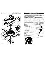
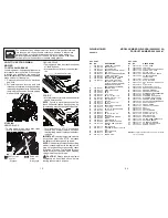
REPLACING BATTERY
WARNING:
Do not short bat tery ter mi-
nals by al low ing a wrench or any other object
to contact both terminals at the same time.
Before con nect ing battery, remove metal
bracelets, wrist watch bands, rings, etc.
Positive terminal must be connected first to
prevent spark ing from ac ci den tal grounding.
1. Lift seat pan to raised position.
2. Remove terminal cover.
3. Disconnect BLACK battery cable then
RED battery cable, battery strap and
carefully remove battery from riding
mower.
4. Install new battery with terminals in same
position as old battery.
5. Reinstall terminal cover.
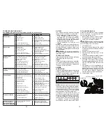
6. First connect RED battery cable to
positive (+) battery terminal with bolt and
nut as shown. Tighten securely.
7. Connect BLACK grounding cable
to negative (-) bat tery terminal with
remaining bolt and nut. Tighten securely
8. Lower seat pan.
Seat Pan
Nut
Nut
Positive
(Red)
Cable
Negative
(Black)
Cable
Bolt
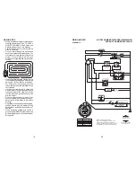
INTERLOCKS AND RELAYS
Loose or damaged wiring may cause your
riding mower to run poorly, stop running, or
prevent it from starting.
• Check wiring. Ensure all wiring and con-
nectors are secure.
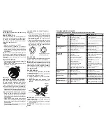
ENGINE
Your carburetor is not adjustable. If your
engine does not operate properly due to
suspected carburetor problems, take your
riding mower to a qualified service center
for repair and/or adjustment.
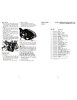
TO START ENGINE WITH A WEAK
BAT TERY
CAUTION:
Lead-acid batteries gen er-
ate ex plo sive gases. Keep sparks, flame
and smoking ma te ri als away from bat ter ies.
Always wear eye pro tec tion when around
batteries.
If your battery is too weak to start the engine,
it should be recharged. (See "BATTERY" in
the Maintenance section of this man u al).
21
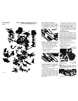
SERVICE AND ADJUSTMENTS
RIDING MOWER
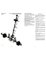
TO REMOVE MOWER
1. Place deck clutch in “DISENGAGED"
position.
2. Move mower height adjustment lift lever
forward to low er mower to its lowest
po si tion.
3. Remove mandrel cover.
4. Remove pins holding left and right front
mower suspension arms in place.
5. Remove bolt holding deck front to rear
leveling rod in place.
WARNING: TO AVOID SERIOUS INJURY, BEFORE PERFORMING ANY
SER VICE OR AD JUST MENTS:
1. Depress clutch/brake pedal fully and set parking brake.
2. Place motion control lever in neutral (N) position.
3. Place deck clutch in “DISENGAGED” position.
4. Turn ignition key to “STOP” and remove key.
5. Ensure the blade and all moving parts have completely stopped.
6. Disconnect spark plug wire from spark plug and place wire where it cannot
come in contact with plug.
TO INSTALL MOWER
Install in reverse order following instructions
in "TO REMOVE MOWER" section.
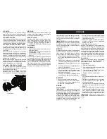
6. Remove pin holding deck lift link arm in
place.
7. Remove bolt holding deck side to side
leveling rod in place.
8. Remove belt from around pulleys.
9. Slide deck out from under side of mower.
Deck Leveling
Side to Side
Rod Bolt
Mandrel Cover
Deck Lift
Link Pin
Front Leveling
Rod Bolt
Mower
Suspension
Arm Pin