47
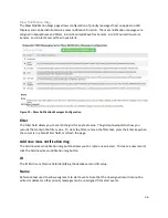
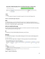
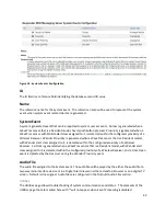
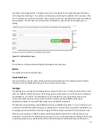
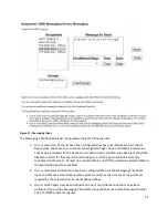
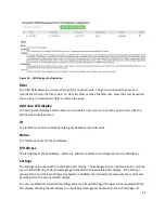
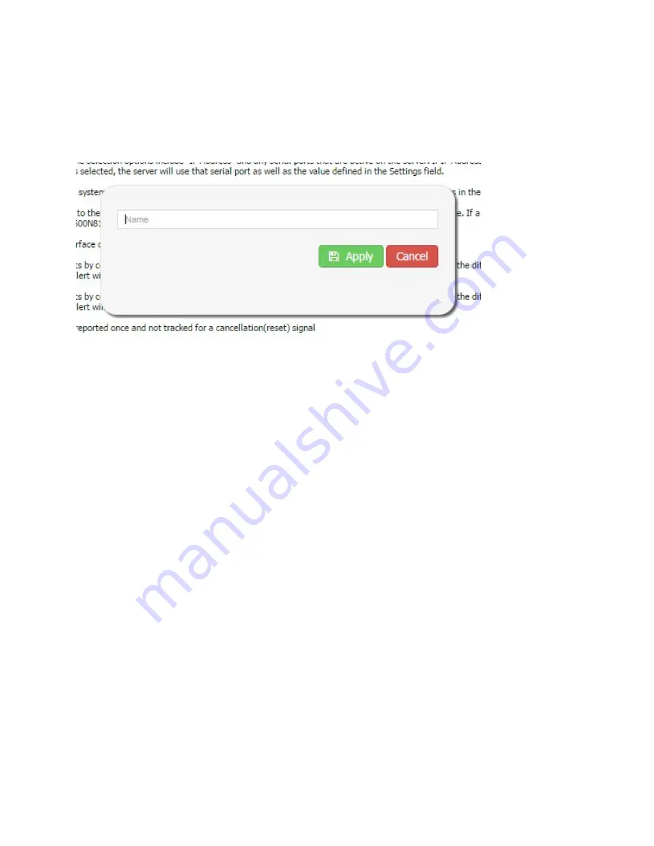
then click on the Apply button. The Name value can be changed later by simply clicking on the Name
cell in the grid and editing it. You will see another popup confirming the addition of the new row. Click
on the confirmation window’s OK button, then you will see the new row added to the grid, with default
values applied. The Add new row button may be renamed to represent the element type you are
adding.
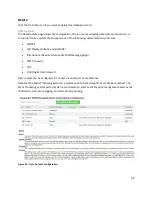
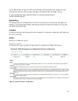
Figure 24 - Add New Row Popup
ID
The ID field is a reference field identifying the database record ID value
Name
The reference name for the Data input.
Input Interface
The input interface used to communicate with the selected data input. The selection options include
"Ethernet" and any USB based serial ports that are active on the server.
Settings
The Settings value used by the selected system to connect to the server. If an Ethernet interface is used
with TAP, COMP2 or SMTP protocols, the Settings value should represent an IP Port value, formatted as
port=NNNN, e.g. port=3737. If a USB based serial port interface is used, the Settings value should
contain the baud and parity of the serial connection, formatted as baud=NNNN, parity=aaaa,
databits=N, stopbits=N, e.g. baud=9600, parity=none, databits=8, stopbits=1.
The default serial port setting is baud=9600, parity=none, databits=8, stopbits=1. You can choose to use
a subset of this definition when defining your Settings value. As an example, to operate at 2400N81, you
could simply use baud=2400 and the remaining part of the settings is assumed from the default values.
With Inovonics protocol or COMP1 protocol, the Settings field should include a tolist parameter, e.g.
tolist=101, or tolist=103;114. With Inovonics protocol, you can route low battery and tamper alerts using
a maintlist parameter, e.g. maintlist=112. When the tolist and/or maintlist parameters contain more

