


30
CHAPTER 4
•
WEB INTERFACE
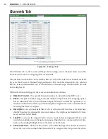
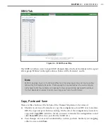
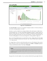
Channels Tab
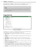
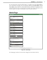
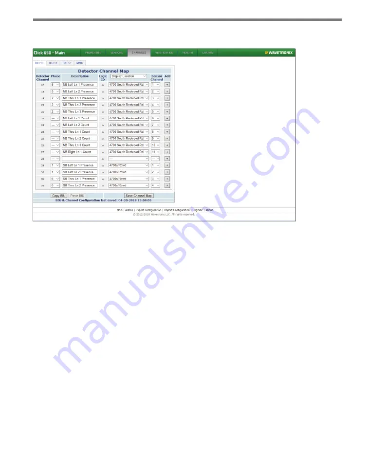
Figure 4.3 – Channels Tab
The Channels tab is where users will map the incoming sensor channels from any of the
four attached sensors to outgoing detector channels.
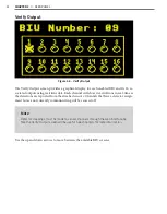
The Click 650 and 656 have four available BIUs (9–12) with 16 detector channels available
for each. The Detector Channel Map grid shows all 16 available channels for the selected
BIU ID. Select a different BIU tab to switch detector channel maps. (Disabled BIU IDs will
not be displayed.)
Within the Channel Map grid, there are seven individual columns.
•
Detector Channel –
The specific channel number (1–64) within this BIU to use.
•
Phase –
The phase number assigned to this channel output. Note that assigning a phase
has no functional effect on the channel output, but may be useful for operators to re-
member which channel lines up with which phase assignment on the controller that is
receiving the detector outputs.
•
Description –
An optional field that can be used to describe the lane or location han-
dled by this detector channel for user convenience. Descriptions are limited to 32 char-
acters and can be left blank.
•
Logic ID –
Letter (a–l) assigned to this sensor/sensor channel assignment. This is only
used when multiple sensor channels are assigned together to a common detector chan-
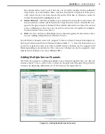
nel (see the Adding Multiple Sensor Channels section below).
•
Sensor Selection –
Each row drop-down will contain listings for each attached sensor.
Select the sensor from which this channel will be assigned. The drop-down list above
Summary of Contents for Click 65 Series
Page 1: ...Click 65x Series USER GUIDE...
Page 5: ......
Page 25: ......
Page 45: ......
Page 49: ...48 APPENDIX Figure A 3 TS2 Type 2 Operating like a TS1...


