


15 of 23
WX-501-0552 • 01.22
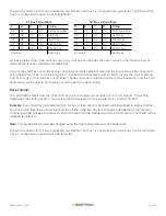
If the Click 111 is successful in communicating with a SmartSensor, it will display the baud rate found, using the
same Level 2 LED system used in selecting the baud rate (covered in the Baud Rate section and the table below).
After a short time of displaying the autobaud results, the menu will return to normal operation.
If the autobaud fails, all four Level 2 LEDs will flash once, and then the menu will return to normal operation.
Note.
If the baud rate of either of the RS-485 buses was configured using the DIP switches (so that parameter is
set to Hardware mode), the Level 2 LED configuration options for that bus will not be displayed (the LED option
will never come on). If both RS-485 buses are configured using the DIP switches, the Level 1 LED menu option for
autobaud will not be displayed (the green LED option will never come on).
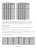
Baud Rate (Bus 1 and 2)
The next parameters we’ll talk about allow you to manually set the baud rate of the two RS-485 buses. Bus 1 comes up
first, with the green and yellow LEDs coming on together; bus 2 comes up second, with the blue LED glowing solid.
Note.
This parameter can also be changed using the DIP switches or Click Supervisor.
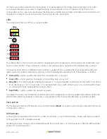
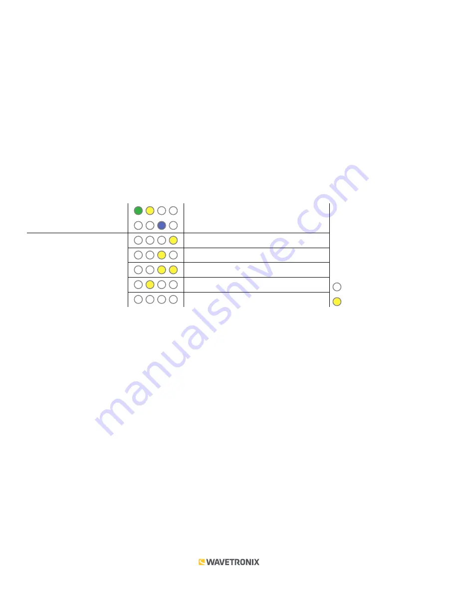
Level 1 LEDs
Baud rate for bus 1
Baud rate for bus 1
Level 2 LEDs
9600 bps (default)
19200 bps
38400 bps
57600 bps
LED off
Cancel and exit menu
LED on
Navigating through the Menu and the Menu Operation Example sections for how to configure this parameter.
Because this parameter can also be set by the DIP switches, you may need to ensure that the DIP switches are
set to Software configuration mode; if they are set to Hardware, the front panel menu will be able to display but
not change these settings.
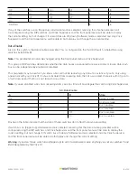
Base Channel
The next parameter on the front panel menu label is the base channel. This can be set independently for the two
buses. To select this parameter for bus 1, release the push-button when the yellow and blue LEDs both come on
solid; for bus 2, release the push-button when the green and blue LEDs both come on solid.
Note.
This parameter can also be changed using the DIP switches or Click Supervisor.
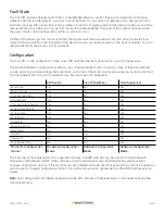
This parameter selects how the Click 111 maps the incoming sensor outputs to the card’s outputs. The setting
determines the starting sensor channel that will be mapped to the associated bus channel 1 output.
Example.
If you have this parameter set to 3 for bus 1, then sensor channel 3 will be mapped to output channel
1 on bus 1. And then the card will count up from there: if the bus has four channels allocated to it, then sensor
channel 4 will be mapped to output 2, sensor channel 5 will be mapped to output 3, and sensor channel 6 will be
mapped to output 4.


