9 of 23
WX-501-0552 • 01.22
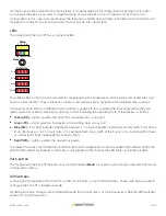
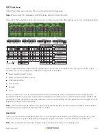
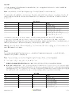
S1: Bus 1 Base Channel
1
2
3
4
Base Channel
Off
Off
Off
Off
Software mode
Off
Off
Off
On
1
Off
Off
On
Off
3
Off
Off
On
On
5
Off
On
Off
Off
7
Off
On
Off
On
9
Off
On
On
Off
11
Off
On
On
On
13
On
Off
Off
Off
15
On
Off
Off
On
17
On
Off
On
Off
19
On
Off
On
On
21
On
On
Off
Off
23
On
On
Off
On
25
On
On
On
Off
27
On
On
On
On
29
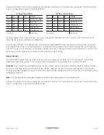
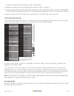
S2: Bus 2 Base Channel
5
6
7
8
Base Channel
Off
Off
Off
Off
Software mode
Off
Off
Off
On
1
Off
Off
On
Off
3
Off
Off
On
On
5
Off
On
Off
Off
7
Off
On
Off
On
9
Off
On
On
Off
11
Off
On
On
On
13
On
Off
Off
Off
15
On
Off
Off
On
17
On
Off
On
Off
19
On
Off
On
On
21
On
On
Off
Off
23
On
On
Off
On
25
On
On
On
Off
27
On
On
On
On
29
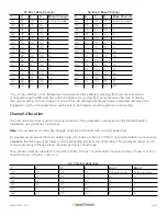
If any of the switches are on (flipped up), Hardware mode is selected, meaning the base channel will be
configured using the DIP switches, and Click Supervisor and the front panel menu will be able to display
the current setting, but not change it. If all switches are off (down), Software mode is selected and only Click
Supervisor and the front panel menu will be able to both display and change the current setting.
Channel Allocation
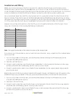
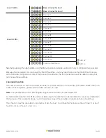
The next set of switches is used in channel allocation. This parameter is configured on the third DIP switch,
labeled S3, using switches 1–4 (S3:1–4).
Note.
This parameter can also be changed using the front panel menu or Click Supervisor.
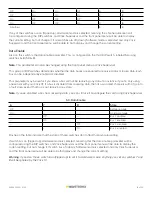
As was discussed earlier, there are sixteen output channels on the Click 111 that can be distributed in various ways
betweeen the two buses (see Table 1 and the preceding text for more information). This parameter allows you to
choose how many of those sixteen channels each bus should have.
The channels must be allocated in increments of two. So bus 1 could have 16 channels and bus 2 have 0, or bus 1
have 14 and bus 2 have 2, and so on.
S3: Channel Allocation
1
2
3
4
Bus 1
Bus 2
Off
Off
Off
Off
Software mode
Software mode
Off
Off
Off
On
16
0
Off
Off
On
Off
14
2
Off
Off
On
On
12
4
Off
On
Off
Off
10
6
Off
On
Off
On
8
8


