background image

2 of 23

WX-501-0552 • 01.22

for which sensor. Be aware that this means there is no dedicated port for configuration, meaning that in order 

to configure the device, you must change the wiring of your cabinet or use a single bus for both data and 

configuration; in this case, data reporting will be temporarily halted during configuration. Be aware that if data isn’t 

received on a Click 111 bus for ten seconds, that bus will go into a fault state.
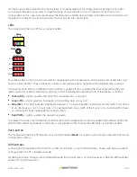
LEDs

The faceplate of the Click 111 has six banks of LEDs.

Mode

Menu

RD TD MF PWR

1  2 3 4


Detection


1—4

5—8

9—12

13—16

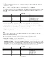
The yellow LEDs in the top bank are used for navigating the front panel menu, which will be discussed later, and 

have no other function. They are level 2 indicators and will be used to navigate within selected menu options.

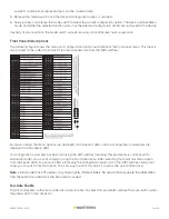
The second bank, with four different colors of LEDs, is used both for navigating the front panel menu (they are 

level 1 indicators used to select menu options) and for indicating the operating state of the device, as follows:


Yellow (RD) –

 Lights up when the Click 111 is receiving data on any port.


Green (TD) –

 Lights up when the device is transmitting data on any port.


Blue (MF) –

 This LED indicates whether the device is in a fault state (MF standing for master fault). If this LED is 

lit up, the device is not in a fault state. If it is extinguished, one or both of the buses is in a fault state (the buses 

can enter fault states independently of each other).


Red (PWR) –

 Lights up when the device has power.

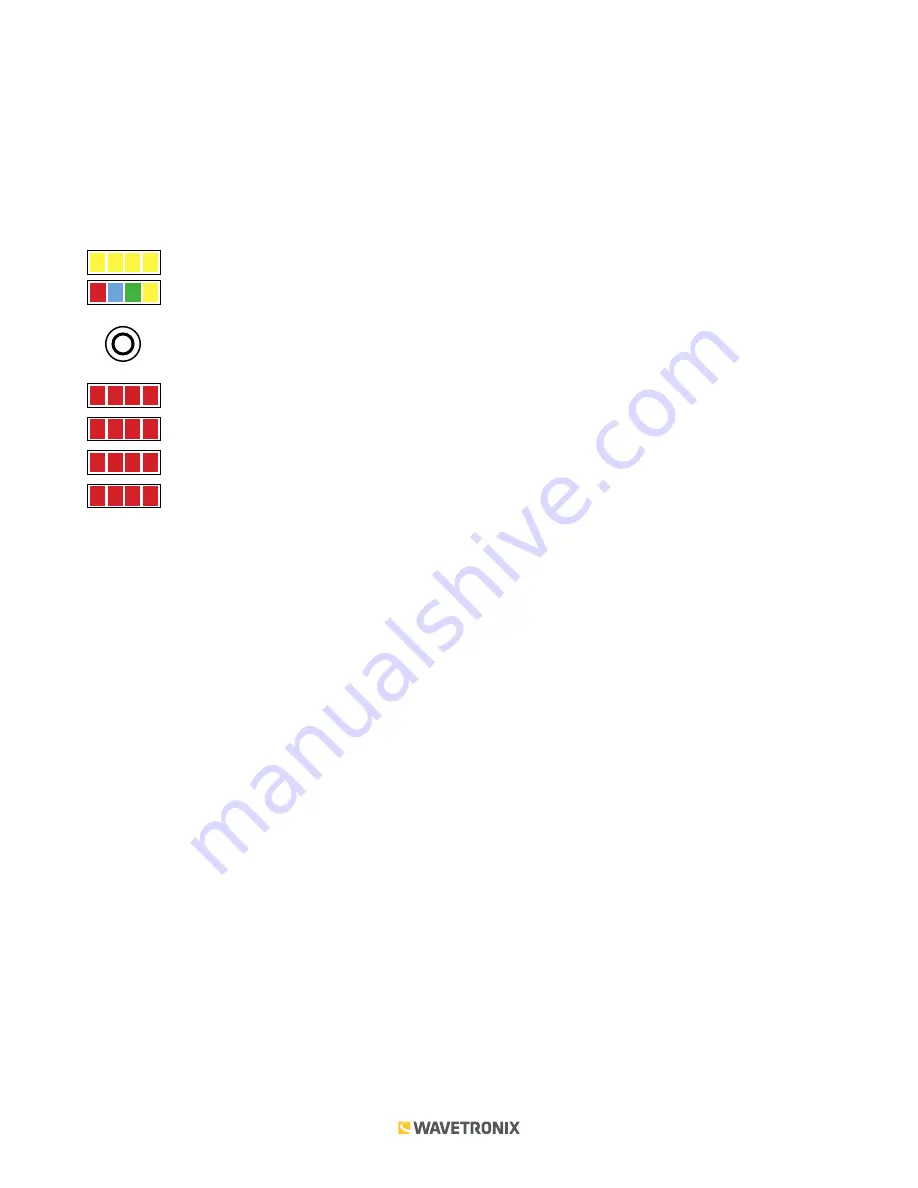
The lowest four banks are for detection indication. Each LED corresponds to one channel (see the numbers next to the 

LEDs for the number assignations), and when a call is placed on that channel, the LED lights up until the call ends.

Push-button

The faceplate of the Click 111 features a push-button labeled 

Mode

. It’s used to cycle through and select menu and 

configuration options.
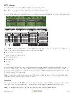
DIP Switches

Just behind the faceplate of the Click 111, on the circuit board, is a set of DIP switches. These switches are used to 

configure the Click 111 in Hardware mode.

All settings are also configurable via Software mode (front panel menu, or Click Supervisor). See the DIP Switches 

section for more information.

Summary of Contents for Click 111

Page 1: ...thers 9600 5 6 7 8 1 2 3 4 0 0 0 0 SW 0 0 0 1 1 0 0 1 0 3 0 0 1 1 5 0 1 0 0 7 0 1 0 1 9 0 1 1 0 11 0 1 1 1 13 1 0 0 0 15 5 6 7 8 1 2 3 4 1 0 0 1 17 1 0 1 0 19 1 0 1 1 21 1 1 0 0 23 1 1 0 1 25 1 1 1 0...

Page 2: ...of the device as follows Yellow RD Lights up when the Click 111 is receiving data on any port Green TD Lights up when the device is transmitting data on any port Blue MF This LED indicates whether the...

Page 3: ...put channels will be covered later So as long as one of these options suits your needs for output channels using a single Click 111 as outlined below will work just fine 1 If you re using hardware con...

Page 4: ...vered in the DIP Switches section 2 Insert two cards into the rack 3 Connect a patch cable from one of the RJ 11 jacks labeled Bus 1 on the faceplate of the first Click 111 to the surge protector Clic...

Page 5: ...onnection A6 No connection A7 Fault Status Out A8 No connection A9 DC common A10 No connection A11 DC common A12 Channel 5 normally open A13 No connection A14 DC common A15 Channel 9 normally open A16...

Page 6: ...ing multiple configuration methods and some of them can only be set using one particular method The table below lists how each parameter may be accessed and configured DIP Switch Front Panel Menu Clic...

Page 7: ...to choose between Hardware Software modes If Software mode is selected the parameter must be configured using the front panel menu or Click Supervisor If Hardware mode is selected the parameter can b...

Page 8: ...he front panel menu will be able to display the current setting but not change it If all switches are off down Software mode is selected and only Click Supervisor and the front panel menu will be able...

Page 9: ...the current setting but not change it If all switches are off down Software mode is selected and only Click Supervisor and the front panel menu will be able to both display and change the current set...

Page 10: ...know a bus will not be receiving any data for instance if you re only using one sensor with your Click 111 If a bus is disabled from receiving data then its associated channels will not go into a faul...

Page 11: ...e front panel menu will be able to both display and change the current setting Warning If you don t have switch 1 on flipped up to set it to Hardware mode anything you set on switches 2 and 3 will be...

Page 12: ...bank will be referred to as Level 2 and is used in configuring the menu options Mode Menu RD TD MF PWR 1 2 3 4 Detection 1 4 5 8 9 12 13 16 Note The multicolored LEDs also function as activity status...

Page 13: ...hes As shown above the menu options are displayed on the Level 1 LEDs and the configuration parameters are displayed on the Level 2 LEDs If a configuration parameter has been set using the DIP switche...

Page 14: ...bled Bus 1 Data Enabled Bus 2 Data Disabled Bus 1 Data Disabled Bus 2 Data Enabled Bus 1 2 Data Enabled Default LED off Cancel and exit menu LED on See the Navigating through the Menu and the Menu Ope...

Page 15: ...ud rate for bus 1 Level 2 LEDs 9600 bps default 19200 bps 38400 bps 57600 bps LED off Cancel and exit menu LED on Navigating through the Menu and the Menu Operation Example sections for how to configu...

Page 16: ...ey are set to Hardware the front panel menu will be able to display but not change these settings Channel Allocation The next parameter on the front panel menu label is channel allocation To select th...

Page 17: ...an also be changed using the DIP switches or Click Supervisor This parameter lets you choose the polarity of the calls placed by the Click 111 A call can be indicated by either high voltage or low vol...

Page 18: ...d red LEDs come on solid Note This parameter can also be changed using the DIP switches or Click Supervisor This parameter lets you choose whether the device will go into a fault state at all If fault...

Page 19: ...the Navigating through the Menu and the Menu Operation Example sections for how to view this parameter After the Click 111 has reset to factory defaults it will check the DIP switches if any of them a...

Page 20: ...ation about your device The tab has the following parameters see the figure and table below Note This parameter can only be configured using Click Supervisor Setting Description Module Allows you to e...

Page 21: ...e and table below Note These parameters can also be configured using the DIP switches or the front panel menu if in the DIP switches they are set to Hardware mode the parameters will appear grayed out...

Page 22: ...is low or high when the output is asserted Chan Out Polarity Lets you choose the polarity of the output channels whether the voltage is low or high when there is a call on that channel Fault Enable Le...

Page 23: ...ve your settings return to the Select Driver screen and more The Save menu allows you to save your settings Select Save to File to save your settings to a file Selecting this will open a directory box...

Reviews: