background image

9

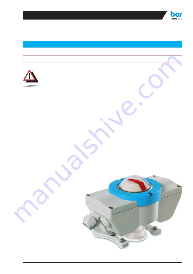
Mounting on the actuator:

When mounting the limit switch box onto the actuator interface, it is impe-
rative to take note of the rotational direction of the actuator pinion, becau-
se incor rect mounting of round initiators can lead to damage to the initiator 
and drive. Take care for stress-free mounting of the bar-switchcontrol with 
the actuator!

Attention!

1a.

  For the mounting on actuators which 

correspond with the provided adjusted  
mounting measures unscrew the back- 
sided screws, set the bar-switchcon-
trol onto the actuator and tighten the 
screws again.

1b.


For mounting onto actuators, whose 
connection dimensions differ from tho-
se of the mounting feet dimensions 
provided, then follow the instructions 
below: 
 •  Loosen and remove the two fixing 

screws.

     •  Slide the mounting feet along the 

guide to reach the desired height.

    •  

If distance between the mounting 
feet is not correct, then change over 
to reach the desired width.

    •  Take fixing screws and washers and 

fix in position.

2.  

Place the bar-switchcontrol onto the 
actuator interface and fix in position 
using the fixing screw set provided.

Summary of Contents for bar switchcontrol SC-M2

Page 1: ...switchcontrol bar gmbh de Operating mounting and adjusting instruction Original operating manual...

Page 2: ...e actuator Before installing i e commissioning the unit described in this document check the technical parameters especially the electrical connection values of the ap plied sensors Take note of the d...

Page 3: ...fitters The fixings can break under these loads bar GmbH Auf der Hohl 1 D 53547 Dattenberg Germany Tel 49 0 2644 9607 0 Fax 49 0 2644 960735 E Mail bar info wattswater com Safety Regulations 2 Techni...

Page 4: ...uminium resin coated Polycarbonat PC with ATEX model anti static coated stainless steel A2 Polyamid PA ABS PC ATEX model excl plate Protection type IP 67 Temperature range 20 C to 70 C low temperature...

Page 5: ...mped 1 mA undamped 3 mA NAMUR opener yellow switch position display LED Pepperl Fuchs NCN4 12GM35 N0 EC type examination certificate PTB 00 ATEX 2048 X and ZELM 03 ATEX 0128 X You find the ATEX certif...

Page 6: ...lgear EN 60947 5 2 Part 5 2 Control circuit devices and switching elements Low voltage switchgear and controlgear EN 60947 5 6 Part 5 6 Control circuit devices and switching elements DC interface for...

Page 7: ...devices and switching elements Low voltage switchgear and controlgear EN 60947 5 6 Part 5 6 Control circuit devices and switching elements Explosive atmospheres EN 60079 0 Part 0 Equipment General re...

Page 8: ...VDI VDE 3845 The dimensional width is achieved by ha ving the feet mounted either inwards or outwards Fig 1 and 2 and the height is adjusted by sliding the mounting feet along the guides on the side o...

Page 9: ...g measures unscrew the back sided screws set the bar switchcon trol onto the actuator and tighten the screws again 1b For mounting onto actuators whose connection dimensions differ from tho se of the...

Page 10: ...e to observe the connection data for the switch and or in itiator Connecting Electrical connection for the bar switchcontrol Connecting round initiators Type SC D and SC N Connection diagram for round...

Page 11: ...alloca ted the Open Position of the valve The lower operating cam actuating ele ment actuates the lower ranking switch on the bar bar switchcontrol terminal 1 3 which is preferentially allocated the C...

Page 12: ...ion of terminals 7 and 8 is as per connection diagram Solenoid valve con nection equal for all types Connection of slot initiators type SC NS Attention Connecting Connecting slot initiators Type SC NS...

Page 13: ...e cam set ting this can be found in the actuating shaft After the position setting the adjusting tool E must not be rotated Additionally it must be then pulled out and inserted into the deeper recess...

Page 14: ...tes a signal a few degrees before reaching the end positi on Then set the other actuating device slightly less than 90 to the first actua ting device see picture this page Take the valve to the other...

Page 15: ...ng to fig B page 12 3a The switch is already operated damped I Turn the adjusting tool anticlockwise until the switch is no longer actuated damped II Keep on turning until switching point is reached I...

Page 16: ...Round initiator Spare part set No 5 Actuating shaft Slot Initiator 3 pieces 3 pieces 3 pieces 6 pieces Actuating shaft O Ring Adjusting tool Switching cam Actuating device Slot initiator Spare part se...

Page 17: ...uip the spare actuating shaft with the sup plied parts and insert in the housing Mountthebar switchcontrol setthecams and remake the electrical connection Type SC M2 Connect to lower switch at 1 2 3 C...

Page 18: ...cam with the actuating device and push onto the spare actu ating shaft Take care to observe that the actuating devices with their sides are next to one another Mount the bar switchcontrol set the ac...

Page 19: ...m the terminal block Exchange micro switches and reconnect according to the circuit diagram on the inner side of the housing Replace mounting plate into the hou sing Push the cam onto the actuating sh...

Page 20: ...rms and Conditions of Sale and Delivery which has been com municated to the Purchaser in any form without the written consent of a Watts representative Warranty The bar products are comprehensively te...

Reviews: