background image


11

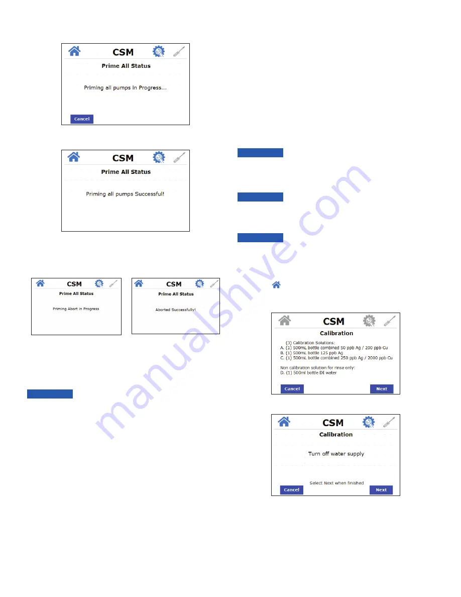
4.  A status message will appear letting you know priming  

is in progress. 

5.  Once priming is complete, another status message will appear 

letting you know priming was completed successfully.

6.  If at any time, priming needs to be aborted, press 

Cancel

. A status 

message will appear letting you know priming is being aborted. 

Then another status message will let you know priming was  

aborted successfully.

6.3 Taking Readings

Once priming has been completed successfully, the CSM is ready to 

take readings. CSM will take readings manually or automatically at 

preset intervals, depending on the setting. See Setting the Reading 

Mode section for more information.

7.0 Maintenance

7.1 Calibration

The CSM was tested and calibrated prior to leaving the factory. The 

instrument operates from a predetermined calibration curve for high 

accuracy. Calibration is recommended every 3 months or every time 

the reagents are replaced.
When performing calibration, a calibration kit (p/n 28159S) is necessary. 

The calibration kit includes:

•  Low Range Copper/Silver (500 ml) (

Solution A

 in Cal Procedure)

•  Mid Range Silver (500 ml) (

Solution B

 in Cal Procedure)

•  High Range Copper/Silver (500 ml) (

Solution C

 in Cal Procedure)

•  DI Water (500 ml) (

Solution D

 in the Cal Procedure)

To recalibrate the CSM, follow the prompts on the screen. 
1.  From the 

 screen, press 

Service

 to enter the Service Menu.

2.  Press 

CALIBRATE

 to begin the Calibration sequence. Ensure you 

have the calibration kit ready, then press 

NEXT

.

3.  Turn off the water supply. Press 

Next

.

There is a removable light shield attached to the optical block to 

help prevent light from entering the optical block and affecting the 

readings. Be sure this shield is in place at all times when taking 

readings or doing a calibration to ensure reading accuracy.

NOTICE

There is a removable light shield attached to the optical block to 

help prevent light from entering the optical block and affecting the 

readings. Be sure this shield is in place at all times when taking 

readings or doing a calibration to ensure reading accuracy.

NOTICE

To ensure there is enough solution to complete the calibration, 

be sure that the Line Flush Duration setting is set to 10 seconds. 

See Adjusting the Line Flush Duration section in this manual for 

instructions on how to adjust this setting.

NOTICE

If new reagent was just installed in the CSM, be sure that the CSM 

has been primed and the new reagent is in the lines to ensure the 

new reagent is being used for the calibration procedure.

NOTICE

Summary of Contents for 28062

Page 1: ...ilver Monitor IS HF CSM 100184 WARNING Read this Manual BEFORE using this equipment Failure to read and follow all safety and use information can result in death serious personal injury property damage or damage to the equipment Keep this Manual for future reference Rev 1 ...

Page 2: ...ing the Units of Measurement 7 5 3 Setting the Date Time 7 5 4 Adjusting the Brightness 7 5 5 Setting the Time Schedule 7 5 6 Setting the Reading Mode 8 5 7 Adjusting the Line Flush Duration 8 5 8 Security Setting 8 5 9 Firmware Update 9 5 10 Copying FRAM data to SD Card 9 5 11 Factory Reset 10 5 12 About Device 10 6 0 System Start Up 10 6 1 Prepare Reagents 10 6 2 Priming the CSM 10 6 3 Taking Re...

Page 3: ...nt This pictorial alerts you to the need to read the manual This pictorial alerts you to electricity electrocution and shock hazards 1 0 Understanding Safety Information This manual contains safety and use instructions that must be followed during the installation commissioning operation care and maintenance and service of the CSM All responsible personnel must read this manual prior to working wi...

Page 4: ...o 23 hours 59 minutes Path Length 10mm Display 3 5 Color graphic touch screen Analog Output Powered 4 20mA 1000 Ω drive isolated Maximum Water Pressure 124 kPa 18 psi see Plumbing Connections section Flow Rate 185 ml min to 225 ml min 044 to 059 Gal min Operating Temperature 1 C 50 C 34 F 122 F Max Sample Water Intake and Drainage Flow 225 ml minute Wetted Materials PBT Polypropylene 316 Stainless...

Page 5: ...be removed for easier connections Please ensure this terminal set is properly tightened using the two side screws 3 2 Plumbing Connections All plumbing connections are made with user supplied OD tubing using the push to connect fittings attached to the CSM All water tubing used to connect to the CSM is supplied by the installer Sample water should be particulate free The sample water supply does n...

Page 6: ...electrical panel and tighten Securing the Electrical Enclosure Once all electrical connections are made the electrical panel must be secured by closing the compartment and tightening the captive Phillips screw 4 0 Commissioning and Start Up 1 Once all water and electrical connections have been made turn on power to the CSM 2 The CSM will run through a startup process that takes less than 10 second...

Page 7: ...ve 4 Once the date and time have been saved press the button to return to the home screen or press Cancel to return to the previous menu 5 4 Adjusting the Brightness The screen brightness can be adjusted to provide easier readability of the display in low light or no light conditions There are 10 brightness levels available To adjust the screen brightness 1 Press Brightness on the Configuration Me...

Page 8: ... suggested line flush duration is 1 second for every foot of sample line tubing assuming inlet pressure of 4 60psi To adjust the line flush duration 1 Press Line Flush Setting on the Configuration Menu screen 2 Using the up and down arrows set the desired duration for the line flush in seconds 3 Once the desired Line Flush Duration has been saved press the button to return to the home screen or pr...

Page 9: ...ate is complete a restart of the instrument is required Do not remove the SD card or turn power off while the software update is in progress Doing so can cause an unrecoverable failure NOTICE 5 10 Copying FRAM data to SD Card The following information from the CSM can be transferred to an SD card in CSV file format Readings Error and warning logs with date and time stamps All user settings Calibra...

Page 10: ...he prime sub menu 3 Press the desired priming option If this is the first time starting up the instrument start with Prime Water and repeat this step for all priming options in this menu Reagent Bags Hanging on Brackets P N 110097 Assembled in the USA Reagent Kit Copper Indicator 16260 Airport Park Drive Suite 140 Fort Myers FL 33913 L 74125 Rev E 11 2020 WARNING Harmful if swallowed Causes skin i...

Page 11: ...per Silver 500 ml Solution C in Cal Procedure DI Water 500 ml Solution D in the Cal Procedure To recalibrate the CSM follow the prompts on the screen 1 From the screen press Service to enter the Service Menu 2 Press CALIBRATE to begin the Calibration sequence Ensure you have the calibration kit ready then press NEXT 3 Turn off the water supply Press Next There is a removable light shield attached ...

Page 12: ...placement Kit To order any accessory or replacement parts please contact the HF scientific Customer Service Department HF scientific 16260 Airport Park Drive Suite 140 Fort Myers FL 33913 Phone 239 337 2116 Toll Free 888 203 7248 Fax 239 454 0694 Email hf info wattswater com Website www hfscientific com 4 Disconnect the upper inlet tubing hose from the peristaltic pump and attach a single piece of...

Page 13: ...gent tubing skip to step 16 12 Insert short piece of new tubing into outlet fitting on solenoid valve Insert other end into inlet fitting into optical injector 13 Secure solenoid valve to bracket with 2 screws removed in step 6 14 Insert end of new tubing into inlet of the solenoid valve 15 Reuse Velcro strap to secure the reagent tubing check valves to the top of the pump bracket 16 Guide tubing ...

Page 14: ...the base 9 4 Replacing the Pressure Regulator Assembly Kit 28190S To replace the pressure regulator assembly on the CSM instrument 1 Turn off water to the CSM instrument 2 Loosen the screws on the bracket connecting the pressure regulator to the back panel 3 Lift bracket and attached components from back panel 4 Loosen the water inlet tube orange from the pressure regulator 5 Remove the panel nut ...

Page 15: ...pump to the optical board and then remove air pump 11 Insert new air pump Be sure the arrow on the new air pump is facing the correct direction 12 Install 2 screws from underneath air pump bracket 13 Attach air pump to optical board using the included zip tie 14 Screw in black fitting into air pump outlet 15 Reconnect the black and pink air pump wiring connection located in the electrical panel 16...

Page 16: ...IMPLIED WARRANTIES OR MERCHANTABILITY AND FITNESS FOR A PARTICULAR PURPOSE The remedy described in the first paragraph of this warranty shall constitute the sole and exclusive remedy for breach of warranty and the Company shall not be responsible for any incidental special or consequential damages including without limitation lost profits or the cost of repairing or replacing other property which ...

Reviews: