


Overview
7
C: Neutral.
This terminal “
N
” should be connected to neutral for circuits where neutral is present.
D: Line voltage inputs.
These terminals connect to the
Ø
A
(phase A),
Ø
B
(phase B), and
Ø
C
(phase C) electric mains. On wye models the meter is powered from the
Ø
A
and
N
terminals. On
delta models, the meter is powered from the
Ø
A
and
Ø
B
terminals.
E: Line voltage measurement ratings.
This block lists the nominal line-to-neutral “
Ø-
N 120V
~
”
voltage, line-to-line “
Ø-Ø
240V
~
” voltage, and the rated measurement voltage and category
“
240V CAT III
” for this WattNode model. See the
for more information
about the measurement voltage and category.
F: UL Listing mark.
This shows the UL and cUL (Canadian) listing mark and number “
3KNN
”.
G: FCC Mark.
This logo indicates that the meter complies with part 15 of the FCC rules.
H: CE Mark.
This logo indicates that the meter complies with the regulations of the European
Union for Product Safety and Electro-Magnetic Compatibility.
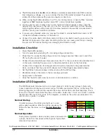
J: Status LEDs.
These are status LEDs used to verify and diagnose meter operation. See
lation LED Diagnostics (p. 22)
for details.
K: Current transformer (CT) voltage rating.
These markings “
0.333V
~
” indicate that the meter
must be used with CTs that generate a full-scale output of 0.333 Vac (333 millivolts).
L: DIP switch.
This DIP switch block is used to set the BACnet MAC (network) address and baud
rate. See
Setting the BACnet Address (p. 20)
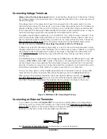
M, N, O: Current transformer (CT) inputs.
These indicate CT screw terminals. Note the white
and black circles at the left edge of the label: these indicate the color of the CT wire that should
be inserted into the corresponding screw terminal. The terminals marked with black circles are
connected together internally.
P: Auxiliary output terminal.
This screw terminal is used for the X terminal options, such as
Option TM1
, which adds support for an external thermistor.
Q: BACnet common terminal.
This is the common or ground terminal for BACnet EIA RS-485
communication wiring. It is also the common for the X terminal options if they are installed.
R: BACnet signal terminals.
These are the RS-485 A– and B+ signals (half-duplex, two-wire).
There are several names for these terminals:
○
Inverting pin
: A–, A, –, TxD–, RxD–, D0, and on rare devices “B”
○
Non-inverting pin
: B+, B, +, TxD+, RxD+, D1, and on rare devices “A”
S: Communication status.
This LED indicates communication status. See
BACnet Communica-
tion Diagnostics (p. 27)
for details.
T: Serial number.
This is the meter serial number. The barcode contains the serial number in Code
128C format.
U: Mains supply rated voltage.
This is the rated supply voltage for this model. The
V
~
indicates
AC voltage. For wye models, this voltage should appear between the
N
and
Ø
A
terminals. For
delta models, this voltage should appear between the
Ø
A
and
Ø
B
terminals.
V: Mains frequencies.
This indicates the rated mains frequencies for the meter.
W: Maximum rated volt-amps.
This is the maximum apparent power consumption (volt-amps)
for this model.
X: Manufacture date.
This is the date of manufacture for this WattNode meter.
Y: Caution, risk of electrical shock.
This symbol indicates that there is a risk of electric shock
when installing and operating the meter if the installation instructions are not followed correctly.
Z: Attention - consult Manual.
This symbol indicates that there can be danger when installing
and operating the meter if the installation instructions are not followed correctly.


