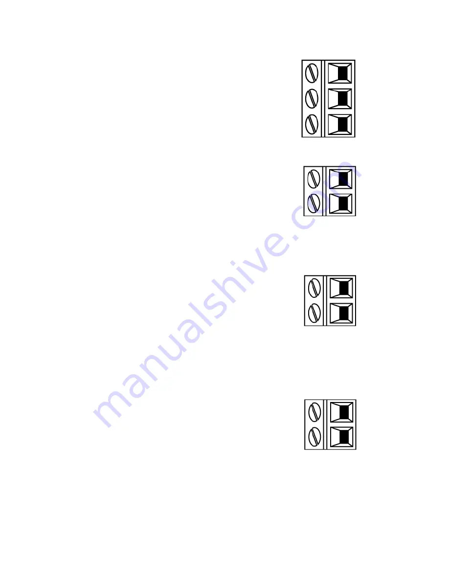
Run status output (J4)
Connect the output device to the C (common) terminal
of the relay connector and either the N/C (normally
closed) or N/O (normally open) terminal as required.
This relay coil is energised when the pump is running.
The default for Relay 2 is run status, on un
models this output (2) can be configured in the control
settings menu.
RLY 2
N/C
3
J4
C
N/O
2
1
Remote stop input (J3)
Apply a signal of 85VAC to 130VAC across terminals AC1
and AC2 to stop the pump. Polarity is not important.
The pump will not run while this signal is applied. In
manual and analog mode, the pump will start when the
signal is removed.
Rem Stop
AC1
2
J3
AC2
1
Speed: analog input (J2)
The analog process signal must be applied to the I/P
terminal of the Analog connector (J2). Ground to the
GND connector of the same terminal. In Analog mode
the pump set speed will be proportional or inversely
proportional to the analog input.
4-20mA circuit impedance: 250Ω.
Max current 40mA
Note:
inverting the signal response is set up in
software. Do not invert the polarity of the terminals.
Analog
GND
2
J2
I/P
1
Speed: analogue output (J1) (Un only)
A current analogue signal within the range 4-20mA is
available between the O/P (output) terminal and the
GND terminal. The current is fixed and directly
proportional to the pump speed. 20mA = maximum
speed, 4mA = zero speed.
There is also an option to match the scale of the 4-
20mA input if this has been reconfigured by the user.
This option is available in the Control settings menu.
Note:
If the mA output is to be used for reading from a
multimeter (set on mA), a 250Ω resistor is required in
series.
4-20mA
GND
2
J1
O/P
1
m-qdos-en-02
38


