background image

Watlow  EZ-ZONE

®

  ST 

    79   

• 

Appendix

Chapter 8: Appendix

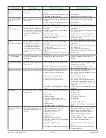
Troubleshooting

Indication

Description

Possible Cause(s)

Corrective Action

Alarm won’t clear or 

reset

Alarm will not clear or reset 

with keypad or digital input 

• Alarm latching is active  

• Alarm set to incorrect output  

• Alarm is set to incorrect source  

• Sensor input is out of alarm set point 

range 

• Alarm set point is incorrect  

• Alarm is set to incorrect type  

• Digital input function is incorrect 

• Reset alarm when process is within 

range or disable latching.

• Set output to correct alarm source 

instance.

• Set alarm source to correct input in-

stance.

• Correct cause of sensor input out of 

alarm range.

• Set alarm set point to correct trip 

point.

• Set alarm to correct type: process, de-

viation or power.

• Set digital input function and source 

instance.

Alarm won’t occur

Alarm will not activate output  • Alarm silencing is active 

• Alarm blocking is active 
• Alarm is set to incorrect output  

• Alarm is set to incorrect source  

• Alarm set point is incorrect  

• Alarm is set to incorrect type

• Disable alarm silencing, if required.
• Disable alarm blocking, if required.
• Set output to correct alarm source 

instance.

• Set alarm source to correct input in-

stance.

• Set alarm set point to correct trip 

point.

• Set alarm to correct type: process, de-

viation or power.

[AL`1]

 Alarm Error

[AL`2]

Alarm state cannot be deter-

mined due to lack of sensor 

input 

• Sensor improperly wired or open 
• Incorrect setting of sensor type 
• Calibration corrupt 

• Correct wiring or replace sensor.
• Match setting to sensor used.
• Check calibration of controller.

Sensor input below low alarm 

set point 

• Temperature is less than alarm set 

point 

• Alarm is set to latching and an alarm 

occurred in the past 

• Incorrect alarm set point 
• Incorrect alarm source

• Check cause of under temperature. 

• Clear latched alarm. 

• Establish correct alarm set point.
• Set alarm source to proper setting.

Sensor input above high 

alarm set point 

• Temperature is greater than alarm 

set point 

• Alarm is set to latching and an alarm 

occurred in the past 

• Incorrect alarm set point 
• Incorrect alarm source 

• Check cause of over temperature. 

• Clear latched alarm. 

• Establish correct alarm set point.
• Set alarm source to proper setting.

[Er;i1]

 Error Input

[Er;i2]


Sensor does not provide a 

valid signal to controller 

• Sensor improperly wired or open 
• Incorrect setting of sensor type 
• Calibration corrupt

• Correct wiring or replace sensor.
• Match setting to sensor used.
• Check calibration of controller.

Limit won’t clear or 

reset

Limit will not clear or reset 

with keypad or digital input

• Sensor input is out of limit set point 

range 

• Limit set point is incorrect 
• Digital input function is incorrect

• Correct cause of sensor input out of 

limit range.

• Set limit set point to correct trip point. 
• Set digital input function and source 

instance.

[LiM]

 Limit Error

Limit state cannot be deter-

mined due to lack of sensor 

input, limit will trip 

• Sensor improperly wired or open 
• Incorrect setting of sensor type
• Calibration corrupt

• Correct wiring or replace sensor.
• Match setting to sensor used.
• Check calibration of controller.

8

Summary of Contents for EZ-ZONE ST

Page 1: ...0 User s Manual Registered Company Winona Minnesota USA ISO 9001 TOTAL 3Y earWarranty CUSTOMER SATISFACTION EZ ZONE ST Integrated Control Loop 1241 Bundy Boulevard Winona Minnesota USA 55987 Phone 1 5...

Page 2: ...ion User s Manual Factory Page Warranty The EZ ZONE ST is manufactured by ISO 9001 reg istered processes and is backed by a three year war ranty to the first purchaser for use providing that the units...

Page 3: ...Menu 32 Limit Menu 32 Monitor Menu 32 Loop Menu 33 Alarm Menu 35 Current Menu 36 Profile Status Menu 37 Chapter 4 Setup Pages 39 Analog Input Menu 40 Digital Input Output Menu 42 Limit Menu 44 Control...

Page 4: ...ion 76 Chapter 8 Appendix 79 Troubleshooting 79 Modbus Programmable Memory Blocks 82 CIP Implicit O to T Originator to Target Assembly Structure 84 CIP Implicit T to O Target to Originator Assembly St...

Page 5: ...daches often encoun tered when using many different components and brands Profile capability Includes ramp and soak with four files and forty steps Communications with PLC PC or HMI ST with optional M...

Page 6: ...he Direction parameter in the Digital Input Output Menu Setup Page The EZ ZONE Remote User Interface RUI has a function or EZ Key on the front panel this too can be configured as a digital input by to...

Page 7: ...protection view the control part number or perhaps cre ate a custom Home Page Profile Page Push and hold the the green Advance key for 6 seconds to enter See the Profile Page for fur ther information...

Page 8: ...s off Silence alarm Alarm clear request Restore user settings Analog Input 1 none Thermocouple RTD 100 1k Process V mV mA PID Controller Optional Ramp Soak max 4 files 40 steps Input Sensor off heat c...

Page 9: ...Integrated Control Loop 1 2 EZ ZONE ST Patent Pending Integrated Control Loop 51 6 mm 2 03 in 87 mm 3 43 in 17 4 mm 0 68 in 126 1 mm 4 97 in 29 5 mm 1 16 in 8 mounting screw 8 mounting screw Front Vie...

Page 10: ...t the ampere ambient tempera ture performance curve EZ ZONE ST Without a Contactor 39 9 mm 1 57 in 35 mm 1 38 in 89 2 mm 3 51 in 126 5 mm 4 98 in 215 1 mm 8 47 in 197 1 mm 7 76 in with 120 and 240Vac...

Page 11: ...rol Loop 1 2 3 4 ON LIMIT OUT 3 SSR STATUS OUT 2 LIMIT OUT 3 SSR STATUS OUT 2 hot hot Process 0 to 10V dc 0 to 50mV dc Input 2 Power Supply Power Supply fuse fuse Output 1 SSR Wiring with a contactor...

Page 12: ...K3 J3 A1 L4 T2 S2 R2 L3 K3 J3 A1 L4 T2 S2 R2 load hot hot fuse fuse 2 1 EZ ZONE ST Patent Pending Integrated Control Loop LIMIT OUT 3 SSR STATUS OUT 2 Indicator Lights Process 0 to 10V dc 0 to 50mV d...

Page 13: ...hermocouple Input 1 N O Output 2 common Output 2 Controller D ut 1 hot neutral fuse 98 99 CF CD CE B5 D6 D5 L2 K2 T1 S1 R1 98 99 CC CA CB B5 D6 D5 L2 K2 T1 S1 R1 L3 K3 J3 A1 L4 T2 S2 R2 L2 K2 T1 S1 R1...

Page 14: ...t conditions to remove power from circuit Internal wiring in an ST with a double pole contactor without a limit ST _ B F _ _ _ _ _ _ _ 1 4 2 5 3 6 contactor contact SSR current sensor to pin 3 below t...

Page 15: ...external contactor ST _ L A _ _ _ _ _ _ _ System with optional RUI using the auxiliary terminals 20 A maximum to operate a secondary load Controller label Heat sink label Base label The model number...

Page 16: ...top of the DIN rail Then rotate the controller to an upright position until the lower flange snaps into place To dismount the controller first use a screwdriver to pull down the small le ver on the b...

Page 17: ...g the solid state relay to the heat sink 2 Place the controller body over the solid state relay and using a Phillips screwdriver replace the four screws securing it 3 Snap the control module in place...

Page 18: ...tate relay to the heat sink 3 With a Phillips screwdriver remove the two screws at the top corners of the controller Replacing the Solid state Relay 1 Using a Phillips screwdriver replace the two scre...

Page 19: ...lock 1 2 3 4 ON Control Address Selection 98 99 CF CD CE B5 D6 D5 L2 K2 T1 S1 R1 L3 K3 J3 A1 L4 T2 S2 R2 2 1 EZ ZONE ST Patent Pending Integrated Control Loop LIMIT OUT 3 SSR STATUS OUT 2 Limit Indica...

Page 20: ...m power consumption without mechanical contactor in system 50VA maximum power consumption with mechanical contactor in system 140VA if using external contactor Input 1 Thermocouple S1 R1 Slot B 20 k m...

Page 21: ...Wire Input 2 Thermocouple S2 R2 Slot A 20 k maximum source resistance 20 M input impedance 3 microampere open sensor detection Thermocouples are polarity sensitive The negative lead usually red must b...

Page 22: ...lly NOTE Terminals L4 and A1 on the limit connector are jumpered at the factory to complete the contactor circuit Additional switches may be wired in series to the terminals WARNING If high voltage is...

Page 23: ...actor 1 2 3 4 ON RTD Input 2 2 wire 3 wire Thermocouple Input 2 N O Output 3 N C Output 3 common Output 3 N O Output 4 contactor Coil 1 ST_ L _ _ _ _ _ _ _ _ all T R RUI T R RUI common RUI common Digi...

Page 24: ...240V ac or 30V dc maximum resistive load 20 mV at 24V minimum load 125 VA pilot duty 120 240V ac 25 VA at 24V ac 100 000 cycles at rated load Output does not supply power for use with ac or dc See Que...

Page 25: ...ccur Watlow EZ ZONE ST 23 Chapter 2 Install and Wire Quencharc Note Switching pilot duty inductive loads relay coils solenoids etc with the mechanical relay solid state relay or open collector output...

Page 26: ...rt Wire common to the common terminal of the EIA 485 port Do not route network wires with power wires Connect net work wires in daisy chain fash ion when connecting multiple devices in a network Do no...

Page 27: ...1 000 000 writes See Saving Settings to Nonvola tile Memory in Chapter 2 Install and Wire Wiring a Serial EIA 485 Network Do not route network wires with pow er wires Connect network wires in daisy c...

Page 28: ...ns Parameter Name Range Modbus less 400 001 offset Data Type Read Write Address when all four DIP switches are set to on 1 to 247 Map 1 Map 2 313 2052 uint RW Baud 9 600 188 19 200 189 38 400 190 Map...

Page 29: ...otocol Identifies unique param eters using either the DeviceNet or EtherNet IP protocol further explana tion below Header Name Definition Profibus Index Identifies unique param eters using Profibus DP...

Page 30: ...bove new capabilities phase angle control user programmable memory blocks etc where intro duced into this product line With the introduction of these new capabilities there was a repacking of Modbus r...

Page 31: ...pes used in conjunction with Profibus DP can be found in the table below For more infor mation pertaining to the use of this protocol with the ST control download the RUI Gateway User Manual by pointi...

Page 32: ...Er Digital Input Output Menu 1 dio Digital Input Output 1 do S Output State di S Event State LiM oPEr Limit Menu 1 LiM Limit 1 LL S Low Set Point Lh S High Set Point Mon oPEr Monitor Menu 1 Mon Monito...

Page 33: ...ew the cause of the most recent error If the Attn message is Er i1 or Er i2 this parameter will display the cause of the in put error nonE None 61 OPEn Open 65 Shrt Shorted 127 E M Measurement Er ror...

Page 34: ...igger the limit 1 999 000 to 9 999 000 F or units 1 128 000 to 5 537 000 C 0 0 F or units 18 0 C Instance 1 Map 1 Map 2 277 726 0x70 112 1 4 39 12004 Inst 1 686 float RWES l st1 L St1 Limit 1 Limit St...

Page 35: ...ol Loop 1 Control Mode Select the method that this loop will use to control off Off 62 AUto Auto 10 MAn Manual 54 Auto Instance 1 Map 1 Map 2 221 1750 0x97 151 1 1 63 8001 Inst 1 1880 uint RWES A tSP...

Page 36: ...3 Inst 1 1904 float RWES ti ti Control Loop 1 Time Integral Set the PID integral for the outputs 0 to 9 999 seconds per repeat 180 0 seconds per re peat Instance 1 Map 1 Map 2 226 1764 0x97 151 1 8 69...

Page 37: ...e 2 Map 1 Map 2 113 1510 0x6D 109 1 to 2 1 19 9001 Inst 1 1480 Inst 2 1530 float RWES No Dis play Alarm 1 to 2 Alarm State Read current state of alarm Startup 88 None 61 Blocked 12 Alarm low 8 Alarm h...

Page 38: ...Lo C Lo Current 1 Low Set Point Set the current value that will trigger a low heater er ror state 1 999 000 to 9 999 000 0 0 Instance 1 Map 1 Map 2 288 1256 0x73 115 1 9 15009 Inst 1 1136 float RWES...

Page 39: ...ly running step 1 to 40 0 none Instance 1 Map 1 Map 2 296 3806 0x7A 122 1 4 22004 Inst 1 2906 Offset 80 uint R S typ S typ Profile Status Active Step Type View the currently running step type UStP Unu...

Page 40: ...9 22009 Inst 1 2916 Offset 80 float RW Ent1 Ent1 Profile Status Active Event Output 1 View or change the event output states off Off 62 on On 63 Off Instance 1 Map 1 Map 2 3826 0x7A 122 1 0xE 14 22014...

Page 41: ...gh Power Scale Fn Output 1 Function ss ti Soft Start Time ALM Set Alarm Menu 1 ALM Alarm 1 to 2 A ty Type sr a Source is a Instance A hy Hysteresis a Lg Logic A SD Sides a LA Latching A bL Blocking a...

Page 42: ...2 7 4007 Inst 1 372 Inst 2 532 uint RWES Unit Unit Analog Input 1 to 2 Units Set the type of units the sensor will measure A tP Absolute Temperature 1540 rh Relative Humidity 1538 Pro Process 75 PWr...

Page 43: ...2 0x11 17 8 4017 Inst 1 392 Inst 2 552 float RWES r hi r hi Analog Input 1 to 2 Range High Set the high range for this function block s output 1 999 000 to 9 999 000 9 999 Instance 1 Map 1 Map 2 63 3...

Page 44: ...Output 68 in Input Voltage 193 iCon Input Dry Contact 44 Output Instance 5 Map 1 Map 2 169 1060 Instance 6 Map 1 Map 2 182 1090 0x6A 106 5 to 6 1 82 6001 Inst 5 1000 Inst 6 1030 uint RWES Fn Fn Digit...

Page 45: ...ce 5 Map 1 Map 2 180 1078 Instance 6 Map 1 Map 2 193 1108 0x6A 106 5 to 6 0xA 10 88 6010 Inst 5 1018 Inst 6 1048 float RWES leu LEv Digital Input 5 or 6 Level Select which action will be interpreted a...

Page 46: ...1 Set Point Limit High Set the high end of the limit set point range 1 999 000 to 9 999 000 9 999 000 Instance 1 Map 1 Map 2 736 0x70 112 1 9 42 12009 Inst 1 686 float RWES SP Ll SP LL Limit 1 Set Poi...

Page 47: ...ped 21 OuEr Over damped 69 Critical Instance 1 Map 1 Map 2 259 1786 0x97 151 1 0x13 19 8024 Inst 1 1926 uint RWES UFA UFA Control Loop 1 User Failure Action Select what the controller outputs will do...

Page 48: ...ing section in Appendix for more information 1 999 000 to 9 999 000 F or units 1 110 555 to 5 555 000 C 10 0 F or units 6 0 C Instance 1 Map 1 Map 2 1797 0x97 151 1 0x18 24 76 8041 float RWES rP rP Co...

Page 49: ...Menu Fn Fn Output 1 to 4 Function Select what function will drive this output oFF Off 62 ALM Alarm 6 heat Heat Control Loop 36 Cool Cool Control Loop 20 LiM Limit 126 Ent A Profile Event Out A 233 Ent...

Page 50: ...2 141 958 Map1 Offset 13 Map2 Offset 30 0x6A 106 1 to 4 0xA 10 88 6010 Inst 1 898 Offset 30 float RWES Fn Fn Output 1 Function Select what function will drive this output oFF Off 62 heat Heat Control...

Page 51: ...ich side or sides will trigger this alarm both Both 13 high High 37 LoW Low 53 Both Instance 1 Map 1 Map 2 103 1456 Instance 2 Map 1 Map 2 119 1516 0x6D 109 1 to 2 4 26 9004 Inst 1 1486 Inst 2 1536 ui...

Page 52: ...ll be monitored oFF Off 62 high High 37 low Low 53 both Both 13 Off Instance 1 Map 1 Map 2 283 1248 0x73 115 1 5 145 15005 Inst 1 1128 uint RWES C Ur C Ur Current 1 Message Enable Display under over r...

Page 53: ...gered 107 F AL Force Alarm level trig gered 218 AoF Alarm Outputs Con trol Loop Off level triggered 220 SiL Silence Alarms edge triggered 108 ALM Alarm Reset edge triggered 6 usr r Restore User Settin...

Page 54: ...on band that will be used in all profile step types The process value must enter the deviation band before the step can proceed 0 0 to 9 999 000 F or units 0 0 to 5 555 000 C 10 0 F or units 6 0 C Ins...

Page 55: ...0x96 150 1 4 17003 Inst 1 2324 uint RWE M hL M hL Communications Modbus Word Order Select the word order of the two 16 bit words in the floating point values hiLo Word High Low 1330 Lohi Word Low Hig...

Page 56: ...e but will have an immediate im pact on the profile that is running How to Start a Profile After defining the profile follow the steps below to run the profile 1 From the Home Page push the Advance Ke...

Page 57: ...Select the hours plus Minutes and Seconds for a timed step 0 to 99 0 Instance 1 Map 1 Map 2 503 4004 Map1 Offset 20 Map2 Offset 100 0x79 121 1 to 40 3 21003 Inst 1 2874 Offset 80 uint RWE Min Min Ste...

Page 58: ...ffset 80 uint RWE JS JS Step 1 to 40 Jump Step Select a step to jump to Step 1 Minimum of 1 1 Instance 1 Map 1 Map 2 514 4022 Map1 Offset 20 Map2 Offset 100 0x79 121 1 to 40 0xC 12 21012 Inst 1 2892 O...

Page 59: ...one instance of a menu no submenus will appear R Read W Write E EE PROM S User Set Display Step Type Description Parameters in Step Type ti ti Step Types Time A Time Step controls at the Target Set Po...

Page 60: ...deep JS Jump Step JC Jump Count Ent1 Event Output 1 Ent2 Event Output 2 End End Step Types End An End Step will end the profile If a profile doesn t include an End Step control will move to the next s...

Page 61: ...the Appendix for more information If there is only one instance of a menu no submenus will appear CUSt FCty Custom Setup Menu 1 to 20 CUSt Custom Setup par Parameter iid Instance ID LoC FCty Security...

Page 62: ...RU TUNE Enable 205 r rt Ramp Rate 177 C hy Cool Hysteresis 170 C Pb Cool Proportional Band 169 h hy Heat Hysteresis 167 h Pb Heat Proportional Band 166 db Dead Band 164 td Time Derivative 163 ti Time...

Page 63: ...g Write Security Set the write security clearance level The user can access the selected level and all lower levels If the Set Lockout Se curity level is higher than the Read Lock out Security the Rea...

Page 64: ...ance 1 Map 1 Map 2 3022 uint RWE diAg FCty Diagnostics Menu pn Pn Diagnostics Model Number Display the model number 14 Instance 1 Map 1 Map 2 0x65 101 1 9 116 1009 dint R reu rEv Diagnostics Firmware...

Page 65: ...2 311 490 0x68 104 1 to 2 0x15 21 4021 Inst 1 400 Inst 2 560 float R ELi o ELi o Calibration 1 to 2 Electrical Input Offset Change this value to calibrate the low end of the input range 1 999 000 to...

Page 66: ...Variable Time Base 71 Phase Angle 71 Soft Start Time 71 Single Set Point Ramping 71 Alarms 72 Process and Deviation Alarms 72 Alarm Set Points 72 Alarm Hysteresis 72 Alarm Latching 72 Alarm Silencing...

Page 67: ...PID settings gener ated by the autotune will be used until the autotune feature is rerun the PID values are manually adjust ed or TRU TUNE is enabled To initiate an autotune set Autotune Request AUt O...

Page 68: ...differing control characteristics at various set points for processes that are not entirely linear Once the PID parameters have been set by the TRU TUNE adaptive algorithm the process if shut down for...

Page 69: ...ion Follow these steps for an RTD input 1 Measure the low source resistance to ensure it is accurate Connect the low source resistance to the input you are calibrating 2 Read the value of Electrical M...

Page 70: ...from 0 to 100 percent with an input of 4 to 20 mA Select the low and high values with Range Low r Lo and Range High r hi Setup Page Analog Input Menu Control Methods Output Configuration Each controll...

Page 71: ...h hysteresis set to 0 the process value would stay closer to the set point but the output would switch on and off more frequent ly and may result in the output chattering On off control can be selecte...

Page 72: ...action is active only when the process value is within twice the proportional value from the set point Adjust the derivative with Time Derivative td Operations Page Loop Menu Time Temperature PID Cont...

Page 73: ...nexpensively approach the effect of analog phase angle fired control Select the AC Line Frequency AC LF Setup Page Global Menu 50 or 60 Hz 100 percent output 10 ON 0 OFF 50 percent output 3 ON 3 OFF 6...

Page 74: ...igh or alarm low set point Alarm hysteresis defines how far the process must return into the normal operating range before the alarm can be cleared Alarm hysteresis is a zone inside each alarm set poi...

Page 75: ...Operations Page default 2 Note The Home and Setup Page lockout levels are fixed and cannot be changed Lock Profiling Page LoC P sets the security level for the Profiling Page default 3 Password Secur...

Page 76: ...ing to the lockout table above 2 roll Rolling Password will change the Cus tomer Code every time power is cycled 3 pas u User Password which is needed for a Us er to acquire access to the control 4 p...

Page 77: ...r will change the parameter s actual value As an example Modbus register 360 contains the Analog Input 1 Process Value See Operations Page Analog Input Menu If the value 360 is loaded into Assembly De...

Page 78: ...ready physically connected to the EZ ZONE ST control click the next button to go on line Note When establishing communications from PC to the EZ ZONE ST control an interface converter will be required...

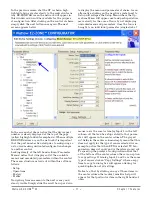
Page 79: ...Simply slide the scroll bar up or down to display the menu and parameter of choice As an alternative clicking on the negative symbol next to Setup will collapse the Setup Menu where the Op erations Me...

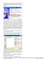
Page 80: ...on someone inadvertently changed a setting without understanding the impact it would be easy and per haps faster to download a saved configuration back to the control versus trying to figure out what...

Page 81: ...ype Calibration corrupt Correct wiring or replace sensor Match setting to sensor used Check calibration of controller Sensor input below low alarm set point Temperature is less than alarm set point Al...

Page 82: ...roller is ramping to new set point Ramping feature is activated Disable ramping feature if not re quired tUNE Autotuning Controller is autotuning the control loop User started the autotune function Di...

Page 83: ...oad is below current trip set point Check that the load current is proper Correct cause of undercurrent and or ensure current trip set point is correct C Er Current Error Load current incorrect Shorte...

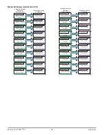
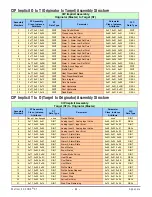
Page 84: ...Loop Set Point Value of Pointer 3 Pointer 4 1480 1481 Alarm 1 High Set Point Value of Pointer 4 Pointer 5 1482 1483 Alarm 1 Low Set Point Value of Pointer 5 Pointer 6 1530 1531 Alarm 2 High Set Point...

Page 85: ...ue of Pointer 29 Pointer 30 1348 1349 Digital Input 6 Status Value of Pointer 30 Assembly Definition Addresses Default Pointers Assembly Working Addresses Pointer 31 1882 1883 Control Mode Active Regi...

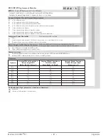
Page 86: ...x01 0x0B REAL 19 0x77 0x01 0x13 DINT Cool Hysteresis 0x97 0x01 0x0C REAL 20 0x77 0x01 0x14 DINT Dead Band 0x97 0x01 0x0A REAL CIP Implicit Assembly Originator Master to Target ST Assembly Members ST A...

Page 87: ...385 C Process 0 to 20 mA 100 or 0 to 10V dc 20 k input im pedance scalable 0 to 50 mV Inverse scaling 20 M input impedance Maximum of 20 k source resistance Maximum of 20 lead resistance for an RTD 42...

Page 88: ...supply B3 Single pole 40 A Watlow contactor 208 240V ac power supply F1 Dual pole 40 A Watlow contactor 24V ac power supply F2 Dual pole 40 A Watlow contactor 110 120V ac power supply F3 Dual pole 40...

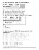
Page 89: ...outputs A None L Limit control module output 3 5A Form C mech relay out 4 2A Form A mech relay B Terminal block access to mechanical contactor coil contacts Power Supply for Mechanical Contactor L For...

Page 90: ...0 __ Series ST Replacement Heat Sink Heat Sink Base Configuration Integrated Mechanical Contactor AA Heat sink for mounting to compact base with no mechanical contactor ordered separately STRT BASE _...

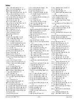
Page 91: ...4 65 70 h Pr Heat Power 33 65 h SP Control Loop High Set Point 47 i CA Calibration Offset 31 66 67 id S Idle Set Point 33 i Er Input Error Latching 42 i Er Input Error Status 31 iP F4 IP Fixed Address...

Page 92: ...mpless transfer 68 C calibrating an analog input 67 Calibration Menu 63 Calibration Offset 31 66 67 chattering output 69 CIP Communications Capabilities 75 CIP Communications Methodology 29 CIP Implic...

Page 93: ...mable Memory Blocks 75 Modbus Word Order 53 model numbers 86 Monitor Menu 32 mounting and unmounting from a DIN rail 14 N National Electric NEC 9 10 network wiring 25 Non volatile Save 39 53 Non Volat...

Page 94: ...61 74 User Programmable Memory Blocks 28 User Restore Set 52 65 User Save Set 52 65 User Tune Aggressiveness 65 Using EZ ZONE Configurator Soft ware 76 using the software 73 V variable time base 71 W...

Page 95: ...or measurement control and laboratory use EMC requirements Industrial Immunity Class A Emissions1 Not for use in a Class B environment without additional filtering EN 61000 4 2 1996 A1 A2 2001 Electro...

Page 96: ...on to pass harmonic current standard 2006 95 EC Low Voltage Directive EN 61010 1 2001 Safety Requirements of electrical equipment for measurement control and laboratory use Part 1 General requirements...

Page 97: ...tlow co uk Website www watlow co uk From outside The United Kingdom Tel 44 115 964 0777 Fax 44 115 964 0071 Asia and Pacific Watlow Singapore Pte Ltd 16 Ayer Rajah Crescent 06 03 04 Singapore 139965 T...

Reviews: