Watlow D4T Data Logger
•
53
•
Chapter 4 Application Examples
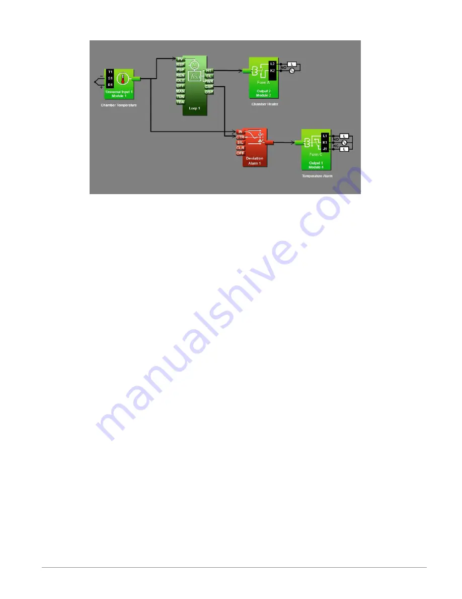
Function Block Diagram
Application Tips:
• Alarm blocks are initially located in the library and can be dragged to the canvas.
• The signal from the universal input to IN on the alarm is the one the alarm monitors
against the alarm set point.
• The signal from CSP on the loop to CTR on the alarm transmits the loop’s set point to
the alarm so that the deviation alarms can be relative to the loop’s set point.
• The signal from the alarm to the output indicates when the alarm has occurred. The
alarm is indicated on the data logger whether or not there is an output attached; the
output on the alarm block is for use with additional logic in the application diagram or
to drive external devices as is shown in this example.
• Enter names for blocks where possible to make the application easier to understand.
• A deviation alarm uses the signal received at CTR as the center of the deviation band.
The high and low alarm set points are relative to that center value. In most devia-
tion alarm applications users want the alarm deviation centered on a control loop’s set
point as shown in this example, but any analog signal could be used.
• Make sure the input block’s Sensor Type and other parameters are set correctly for
your sensor.
• By default the alarm’s type setting is Off. Set it to Deviation Alarm.
• Set the alarm’s Sides setting to High or Low if you want to monitor only for the pro-
cess value going too high or too low, or set Sides to Both if you want the alarm to occur
when the process value is either too high or too low.
• For more information on alarm parameters see the section entitled "
" in Chapter
5.


