


24
|
217
Product Overview
Operation
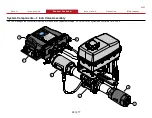
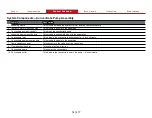
System Components—PDM Control Box Connectors
Feature
Feature
Description
Description
1 Tellurus HMI CANbus
This communicates the CANbus signal to the Tellurus display.
2 Discharge CANbus
This communicates the CANbus signal to the node controllers on each of DLAs.
3 Remote I/O CANbus
This communicates the CANbus signal to an additional node controllers for additional options required in your
application.
4 Diagnostic CANbus
This communicates the CANbus signal to diagnostic equipment, or external CANbus truck control systems for remote
monitoring or control.
5 ATF Temperature
This measures the hydraulic ATF temperature in the reservoir tank.
6 ATF tank level
This monitors the hydraulic ATF level in the reservoir tank.
7 Hydraulic Control
This controls the hydraulic pump that powers the hydraulic motor.
8 Pump discharge pressure
This monitors the pressure in the concentrate manifold after the concentrate pump.
9 Pump speed
This monitors the concentrate pump speed.
10 Pump intake select switch
This signal is provided by the apparatus to determine if the concentrate is source from an on-board or off-board supply.
11 Concentrate tank low
This connects to a tank-level switch that indicates the concentrate supply in the tank is low.
12 Concentrate tank high
This connects to a tank-level switch that indicates the concentrate supply tank is full.
13 Concentrate tank level
This is an optional installer supplied sensor that indicates the concentrate supply level in the tank.
14 Manual override switch—optional This disables the automatic control of the concentrate control valves.
15 Water pressure—optional
This monitors the water pump discharge pressure.
16 Override relay—optional
This 200 A relay enables and disables power to the DLAs—disabling automatic control.
17 PLC 1—power input
This provides power to the primary PLC in the PDM control box.
18 PLC 2—power input, optional
This provides power to the secondary PLC in the PDM control box.
19 Relay power—input, optional
This provides control to the 200 A override relay for toggling between automatic and manual DLA valve control.


