background image


WL2FLT 

Manual                                                                                                                                 Page 12 

 Revision 10-26-2021 

WATERLOGIC MANUFACTURED WATER TREATMENT SYSTEM LIMITED WARRANTY 

UNITED STATES AND CANADA ONLY 


Waterlogic water treatment systems are guaranteed to the original purchaser to be free of defects in 
materials and workmanship for a period of three (3) years from the date of purchase, but in no event 
longer than forty-eight (48) months from the date of manufacture. Waterlogic Commercial Products, 

LLC (“Waterlogic”) bas

ed in the U.S.A. and its affiliated companies are not liable for any cost of 

removal, installation, transportation, or any other charges which may arise in connection with a 
warranty claim. 


This warranty does not cover damage or wear to products caused by abnormal operating conditions, 
accident, abuse, misuse, unauthorized or improper alteration or repair, damage caused by or 
resulting from shipping or accident, damage caused by hot water, freezing, flood, fire, or acts of God. 
The effects from chlorine corrosion, scaling and normal wear are specifically excluded from this 
warranty. This warranty does not cover products used outside the countries where the unit was 
purchased, and does not cover products that were not installed in accordance with Waterlogic printed 
installation and operating instructions obtained in training or from www.waterlogic.us. Failure to 
follow all instructions for operation and maintenance voids the warranty. This warranty is not 
transferable. 


To obtain warranty repairs or replacement, you must obtain a Return Authorization from Waterlogic. 
To obtain a Return Authorization, you must submit a Return Authorization form with supporting 
documentation to Waterlogic for evaluation. The form is available at www.waterlogic.us. Supporting 
documentation must include, but is not limited to; proof of purchase, installation date, failure date, 
and supporting installation and maintenance data.  After you submit a Return Authorization form and 
supporting documentation, Waterlogic will determine whether a reasonably apparent defect in 
materials or workmanship covered by this limited warranty exists. If Waterlogic determines the 
claimed defect is covered by this warranty, Waterlogic will, at its sole discretion, determine whether 
to correct the defect or replace the unit, free of charge to you. If Waterlogic determines that the unit 
should be returned for warranty service, Waterlogic will approve of return in writing and will issue a 
Return Authorization which you must obtain prior to shipping the product. You are responsible for the 
cost of freight in to Waterlogic. 


Waterlogic and its affiliated companies hereby limit the duration of any and all implied warranties to 
a maximum period of three (3) years from the date of purchase including, but not limited to, the 
implied warranties of merchantability and fitness for a particular purpose. Some states do not allow 
limitations on how long an implied warranty lasts, so the above limitation may not apply to you. 
Consequential and incidental damages are not recoverable under this warranty. Some states do not 
allow the exclusion or limitation of incidental or consequential damages, so the above limitation or 
exclusion may not apply to you. 


This warranty gives you specific legal rights and you may also have other rights which may vary from 
state to state. 


New Warranty Policy issued by Waterlogic Commercial Products LLC, USA - January 10, 2014 


Waterlogic Commercials Products LLC


Tel: 

(800) 288-1891


3175 Bass Pro Drive   


Website:  

waterlogic.us 

Grapevine, TX  76051 

Summary of Contents for WL2FLT

Page 1: ...Bass Pro Drive Grapevine TX 76051 800 288 1891 www waterlogicdealers com Tech Portal Website wld portal waterlogic com Waterlogic International LTD Global Headquarters Grenfell Road Maidenhead Berkshi...

Page 2: ...ice personnel who are experienced in the installation function and repair of Waterlogic equipment This publication is written for use by these qualified individuals Waterlogic encourages users to lear...

Page 3: ...scaling 16 Firewall Outlet Solenoid Reverse Flow Orientation 18 Adjusting Cold Water Set Point 19 Programming Disabling Energy Saving Sleep Mode 20 Replacement Components Consumables 21 Counter Top Dr...

Page 4: ...ated installed or maintained The installation maintenance sanitizing and any repair must be performed by qualified persons trained by Waterlogic International or their approved distributors only Do no...

Page 5: ...sanitize before use to eliminate any potential microbiological contaminates CAUTION INDOOR USE ONLY Intended for Household Use Never expose to direct sunlight heat sources or ambient air temperature a...

Page 6: ...Systems are equipped with an extra solenoid to provide redundant protection and reduce accident potential It is also equipped with a leak stop device in the drip tray that will shut off the water sup...

Page 7: ...convert wastewater or raw sewage to drinking water The system is intended to be installed on visually clear water NSF ANSI 55 defines wastewater to include human and or animal body waste toilet paper...

Page 8: ...y Star a US Environmental Protection Agency EPA program that helps our customers save money and protect our climate through superior energy efficiency Waterlogic is certified to ISO 9001 2015 Quality...

Page 9: ...C 41 46 4 F Cold Tank Size Tower 4 Liters 1 Gallon Hot Water Temperature 85 87 C 185 189 F Thermistor Control Hot Tank Hot Tank Size 1 5 Liters 40 Gallons Hot Water Manual Reset Overload 105 C 221 F R...

Page 10: ...3mm x 1176mm 13 74 x 14 29 x 46 30 Weight dry Unit Only 33 0 kg 72 8 pounds ELECTRICAL SPECIFICATIONS ELECTRICAL SUPPLY 120V 60Hz 15 Amp Service COMPONENT POWER approximate AMP DRAW approximate Heater...

Page 11: ...lt water selection Hot Water Double tap and hold the Hot Water Select Button Press release press and hold NOTE Default selection mode is Cold Water Selection will return to default after 3 seconds of...

Page 12: ...c for evaluation The form is available at www waterlogic us Supporting documentation must include but is not limited to proof of purchase installation date failure date and supporting installation and...

Page 13: ...ever operate the UV C emitter if damaged or removed from enclosure Do not touch or look directly into the faucet CAUTION UV LAMPS ARE HAZARDOUS Lamps are considered Hazardous Waste and must be dispose...

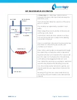
Page 14: ...ir and water to pass into the vent chamber as it is heated Water in the vent chamber is suctioned back through the outlet tube vent hole when water is dispensed Expansion of water as it is heated in t...

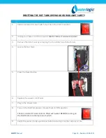
Page 15: ...em 3 Remove the Side Panel by removing the Front Hatch and Side Panels 4 Locate the Hot Tank 5 Press the Reset Button 6 Replace the Lower Front Panel 7 Plug in the Power Cord 8 Turn on the Red Compres...

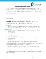
Page 16: ...Hot Tank is made from stainless steel Ensure descaling solution is compatible with stainless and always flush the unit completely Dispose in an environmentally safe manner Materials Needed Personal P...

Page 17: ...tomer s satisfaction WARNING HOT WATER The WL2FLT Water Treatment System produces Hot Water up to 86 C 187 F Water above 52 C 125 F can cause severe burns or scalding Hot water should be dispensed car...

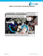
Page 18: ...WL2FLT Manual Page 18 Revision 10 26 2021 FIREWALL OUTLET SOLENOID REVERSE FLOW ORIENTATION...

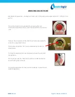
Page 19: ...ew under the decal at the rear of the unit Remove the red portion of the Cold Tank Temperature label to access the adjustment screw The factory set point is 41 F and is indicated by the dot on sheet m...

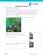
Page 20: ...continuous 3 hour or longer period Selecting any button wakes up the WL2FLT Water Treatment System and turns the heater circuit back on The hot tank will typically take less than 10 minutes to heat t...

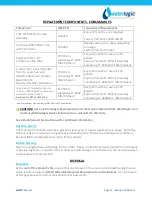
Page 21: ...nt Every 12 months or every 1 250 gallons Factory Part No FT 0035 IL Assembly containing FT 0038 WLT Filter Element One pre installed One required for NSF 42 NSF 53 Certification CAUTION Use only Wate...

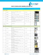
Page 22: ...WL2FLT Manual Page 22 Revision 10 26 2021 WL2FLT TOWER LAYOUT DRAWING AND PARTS LIST Yellow Consumables Green Recommended spare parts Wetted Parts...

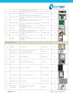
Page 23: ...ing 2 each per 10 units purchased HT 3012 Yes 1 2 12 6900 Overload Metal Cover Recommend stocking 2 each per 10 units purchased ST 8290 Yes 6 PL 0191 L00 BL Black Top Cover Recommend stocking 2 each p...

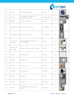
Page 24: ...Yes 16 PU 0017 L00 00 Solenoid Valve MS DC SWV24 01 Recommend stocking 2 each per 10 units purchased PU 0017 L00 00 Yes 17 12 8370 Hot Water Faucet Recommend stocking 2 each per 10 units purchased PL...

Page 25: ...L2FLT Front Down Trim PL 0302 LA0 00 Yes 31 Purchase from John Guest JG Reducing Elbow Connector 5 16 1 4 PI211008S PU 4007 No 32 Purchase from John Guest JG Equal Tee Connector 1 4 PI0208S PU 4011 No...

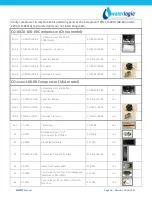
Page 26: ...tor CO 0018 L00 00 Yes CO xxxx L00 00 Compressor USA model 40B 1 CO 0043 I00 00 LG Compressor 120V R134A CSB035LJCM CO 0043 I00 00 Yes 40B 2 ST 0216 L00 00 Capacitor Bracket ST 0216 L00 00 Yes 40B 3 C...

Page 27: ...16 for hot water PL 4064 L00 00 Yes 53 PU 0061 L00 00 Stormtech Mechanical Leak Detector PU 0061 L00 00 Yes 54 ST 0006 L00 WH FW2 RO Solenoid Valve Fixing Bracket ST 0006 L00 WH Yes 55 ST 0004 L00 WH...

Page 28: ...6 FW ST 0007 L00 WH Yes 66 RO 0010 A Flushing Valve Micro RO 0010 A Yes 67 RO 0006 A Rigid Elbow for RO Housing Micro RO 0006 A Yes 68 FU 0010 UVC Sensor Fixing Metal Bracket w Tube FU 0010 Yes 69 FU...

Page 29: ...2021 WL2FLT FZ TOWER WATER FLOW DIAGRAM FILTER BANK SEE FILTER DIAGRAM BELOW SEDIMENT LEAK STOP INLET SOLENOID CARBON BLOCK RO MEMBRANE NO RETURN VALVE FLOW RESITRICTOR FLUSH VALVE DRAIN BULKHEAD DRA...

Page 30: ...ual Page 30 Revision 10 26 2021 WL2FLT ELECTRICAL DIAGRAM DANGER HIGH VOLTAGE ELECTRICAL HAZARD PCB Printed Circuit Board contains High Voltage Only trained and qualified technicians should attempt li...

Page 31: ...terlogic recommends you establish a minimum of weekly visits to the machine for cleaning of the drip tray drain Materials Needed Personal Protective Equipment Rubber or Nitrile Safety Gloves and Prote...

Page 32: ...al Growth UV System Functional Test WARNING ULTRAVIOLET RADIATION Protect your skin and eyes against ultraviolet rays Never look directly at an operating UV light Disconnect wiring before removing 5 R...

Page 33: ...ff Draw a glass of cold water and verify it is has chilled to proper temperature 46F Heater Test 13 Always ensure tanks are full of water before turning on the Heater or the Overload High Limit will o...

Page 34: ...the Red Heater and Compressor Power Switch O OFF to disable the heater and compressor 2 Dispense 2 liters 1 gallon of water through the hot tank to cool the water temperature in the hot tank and avoi...

Page 35: ...Then disconnect the line in the top compartment between the Cold Tank and outlet solenoid 8 Water will begin draining from the Cold Tank once disconnected Once the Cold Tank is empty reconnect the so...

Page 36: ...C 35 F Install indoors and keep unit away from excessive humidity Never expose to freezing temperatures Ensure there is adequate clearance around the unit to allow refrigeration system condenser to di...

Page 37: ...d release the main dispensing button Hot tank is now full CAUTION NEVER TURN ON HEATER BEFORE FILLING HOT TANK Red Compressor Heater Switch must be in the O OFF position while the hot tank is empty Da...

Page 38: ...water in the Leak Tray and will shut down inlet solenoid Possible Reason Solution Water is present in the Bottom Tray causing the leak detection to trigger Leak Detection is on the Counter Top Model...

Page 39: ...e dose of UV Check UV System 1 If Ballast Indication Light is Green the system should be operational Ensure UV lamp is on Replace Lamp If lamp is replaced and problem persists replace UV Sensor 2 If B...

Page 40: ...Orange LED Light Possible Reason Solution Heater is ON Indicator that heater is ON 4 FAULT CODE No LED Light Possible Reason Solution Power Problem Check for power disruption LED Light is out Check th...

Page 41: ...or Power Switch won t light and the Red LED on the Front won t light Possible Reason Solution Circuit Breaker Check the Circuit Breaker Fuse is Blown Replace Fuse Defective Loose Power Cord Check that...

Page 42: ...PCB Defective Red Heater Compressor Switch Replace Red Heater Compressor Switch 3 Compressor Runs But Does Not Chill Possible Reason Solution Condenser is dirty Clean the condensing coil of any obstr...

Page 43: ...ed Heater Compressor Switch on I ON Compressor Starting Circuit Turn Red Heater Compressor Switch off O OFF Remove the compressor cap on side of the compressor Disconnect the black and red terminal co...

Page 44: ...ter 8 Restricted Flow of Hot Water 9 Hot Water Drip out of Faucet 10 Dispenses Hot and Cold Water at the same time 11 No cold water available 12 Water does not dispense from unit 13 No Water is Dispen...

Page 45: ...solenoid to activate not button click Adjust water pressure to 40 60 psi Loose or bad connection on the Front Dispensing PCB or Solenoid Connector Check that they are connected properly and tightened...

Page 46: ...activate not button click Adjust water pressure to 40 60 psi Bad Display PCB Replace Main PCB Debris in the Solenoid Inspect Solenoid for debris and clean out as needed Dispensing Button Stuck Dirt o...

Page 47: ...hod of verification is to turn off water to unit and press the dispense button Does the solenoid open without water pressure to the unit Listen for solenoid to activate not button click Adjust water p...

Page 48: ...ns in the feed line Filters Filters with high pressure drop due to fouling or just by design Change filters more frequently or go to higher micron size filter for local water conditions Restrictions F...

Page 49: ...nd replace tubing as necessary Faucet nipple screen mesh has obstruction s Unscrew faucet nipple from faucet and remove any obstruction s from screen mesh Exhausted Filter Replace the Filter Solenoid...

Page 50: ...more water in than out There is a small hole in the side of the Hot Tank Outlet Tube that allows air and water to pass into the Vent Chamber as it is heated Water in the Vent Chamber is suctioned back...

Page 51: ...Additional method of verification is to turn off water to unit and press the dispense button Does the solenoid open without water pressure to the unit Listen for solenoid to activate not button click...

Page 52: ...er pressure to the unit Listen for solenoid to activate not button click Adjust water pressure to 40 60 psi Closed Water Supply Valve Open the Water Supply Valve Cold Water Solenoid Valve malfunction...

Page 53: ...ged into electrical outlet Check electrical outlet connection or for blown circuit breaker Red Heater Compressor Switch button on unit is in the off position Turn Red Heater Compressor Switch on I ON...

Page 54: ...cold wires on PCB red and blue connections If water now dispenses from the opposite side this is an indication that there is a PCB problem Replace PCB Solenoid If both the Water Pressure and PCB have...

Page 55: ...vate not button click Adjust water pressure to 40 60 psi Cold or Hot Water solenoid valve malfunction Inspect valve components for proper function Replace as necessary Obstruction in solenoid housing...

Page 56: ...egulator Should be 40 60 psi 275 414 kPa Use Pressure Regulator The correct input water pressure is critical to the performance of the unit to allow solenoids to open Outgoing Flow Rate Verify the out...

Page 57: ...aucet The inlet solenoid controls flow into the tanks The tanks will depressurize once the dispense button is released the inlet solenoid closes A small amount of water will Run On through the faucet...

Page 58: ...is too low the High Pressure Switch will never be engaged and the RO system will continually run causing constant water flow to drain Consider installing a booster pump to push the incoming feed press...

Page 59: ...ot Tank is made from stainless steel Ensure descaling solution is compatible with stainless and always flush the unit completely Dispose in an environmentally safe manner Materials Needed Personal Pro...

Page 60: ...tisfaction WARNING HOT WATER The WL2FLT Water Treatment System produces Hot Water up to 87 C 187 F Water above 52 C 125 F can cause severe burns or scalding Hot water should be dispensed carefully int...

Page 61: ...ant has run out Run Compressor for at least ten minutes If Condenser is not warm then refill the refrigerant Compressor problem If Compressor is not running repair or replacement is needed Note The Wa...

Page 62: ...tra Hot capability and the maximum hot temperature is 87 C 189 F It typically takes 10 minutes for the 500W to heat the 1 6 Liter 0 4 Gallon of room temperature ambient water to the 85 C 185 F set poi...

Page 63: ...or zero OHM s on the meter Replace components as necessary Loose or improperly connected wire s to the Heating Element Hot Tank Visually inspect wire leads gong to the hot tank confirm proper connecti...

Page 64: ...3 hour or longer period Selecting any button wakes up the WL2FLT Water Treatment System and turns the heater circuit back on The hot tank will typically take less than 10 minutes to heat the water fro...

Page 65: ...em 3 Remove the Side Panel by removing the Front Hatch and Side Panels 4 Locate the Hot Tank 5 Press the Reset Button 6 Replace the Lower Front Panel 7 Plug in the Power Cord 8 Turn on the Red Compres...

Reviews: