


Components and installation
12.11.2015
14 / 60
Z21826
Copyright
2013 by: WATERKOTTE GmbH. Subject to changes
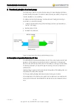
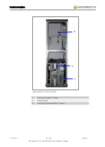
4.3
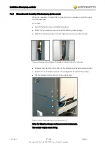
Electrical equipment
The electrical connections are made via the internal terminal (on the construction
profile). The implementation of the electrical cable is carried by the rear wall (with
the strain relief).
The internal terminal connects the entire sensor, all queries, all relay outputs, digi-
tal circuit, the compressor and the electrical heating element. The WATERKOTTE
WWPR-controller is supplied with a control panel mounted on the 24 VAC trans-
former.
An integrated web interface is available for remote monitoring via the Internet.
4.3.1
Electrical resistance heating
Located in the heating flow, power 6 kW. Used to support initial heating in the
winter and during the standby function; automatic or independent control via the
built-in mechanical thermostats.
4.3.2
Domestic hot water heating system
Consisting of: heating circulation pump (speed-controlled / energy class A), air
separator with automat. air diverter, connections for heating flow and return are fit-
ted externally to facilitate installation in the rear panel frame.
4.3.3
Heat source
Consisting of: heat source circulator speed controlled (energy efficiency class A),
connections for ahead and return facilitates installation in the rear wall frame out-
wards.
4.3.4
Electronic heat pump control
The heat pump control (control panel is pictured) is included in the delivery scope
of the WATERKOTTE heat pump.
Use in other than WATERKOTTE heat pumps will void any warranty claim.
The control is used to control and monitor heating systems that are operated with
WATERKOTTE compact heat pumps according to technical guidelines of
WATERKOTTE head pump GmbH.
The following tasks are performed: everything to do with regulation (depending on
the external temperature with pilot room guidance), control, monitoring, self-
diagnosis, saving of data in cases of breakdown.
WATERKOTTE explicitly states that function warranty will become void if used on
systems not approved by WATERKOTTE. Any liability for consequential damages
due to incorrect function within these systems shall be explicitly excluded.
Info: Technical details, operation and warning messages (see
Operating manual
for Heat pump control)
.
4.3.5
Sensors
The control's sensor system consists of: Pressure transmitter for evaporation and
condensation pressure, sensors for temperature detection in all circuits, external
wall sensor in accessories kit, pilot room sensor and hot water sensor (optional).
Summary of Contents for EcoTouch Ai1 Geo
Page 57: ...Technical data 12 11 2015 57 60 Z21826 Copyright 2013 by WATERKOTTE GmbH Subject to changes...
Page 58: ...Technical data 12 11 2015 58 60 Z21826 Copyright 2013 by WATERKOTTE GmbH Subject to changes...
Page 59: ...Technical data 12 11 2015 59 60 Z21826 Copyright 2013 by WATERKOTTE GmbH Subject to changes...


