


560P333P02 REV B
4240 E. La Palma Avenue, Anaheim, CA 92807 • (800) 454-4423 • fax (800) 246-3245 • www.wasteking.com
MANUAL SWITCH
MODEL
VOLTS
WK PART NO.
2000
208-240
2420
2 HP
460
2420
3000
208-240
2421
3 HP
460
2421
5000
208-240
2421
5 HP
460
2421
MAGNETIC SWITCH
MODEL
VOLTS
WK PART NO.
2000
208-240
2416
2 HP
460
2417
3000
208-240
2416
3 HP
460
2417
5000
208-240
2416
5 HP
460
2417
10000
208-240
2416
10 HP
460
2417
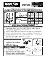
FIG. 12
WIRING FOR THREE PHASE UNITS WITH MANUAL SWITCH
FIG. 13
WIRING FOR THREE PHASE UNITS WITH MAGNETIC SWITCH
NOTES:
1. Motor wired at Factory for 208-240 volts.
For 460 volts, connect motor wires as
shown inside of motor junction box cover.
2. Interchange T1 and T3 to reverse rotation.
3. Magnetic and manual starters, supplied
by Waste King do not require heaters to
complete the circuit. Disposers have
built-in overload protection.
NOTES:
1. Motor wired at Factory for 220-240
volts. For 110-120 volts, connect motor
wires as shown inside of motor junction
box cover.
2. Magnetic and manual starters, supplied
by Waste King do not require heaters to
complete the circuit. Disposers have
built-in overload protection.
NOTES:
1. Motor wired at Factory for 208-240 volts.
For 460 volts, connect motor wires as
shown inside of motor junction box cover.
2. Interchange T1 and T3 to reverse rota-
tion.
3. Magnetic and manual starters, supplied
by Waste King do not require heaters to
complete the circuit. Disposers have
built-in overload protection.
MANUAL SWITCH
MODEL
VOLTS
WK PART NO.
2000
110-120
2420
2 HP
220-240
L-1
L-2
T-1 T-2
L-3
T-3
T-3
L-3
T-2
L-2
3
2
T-1
L-1
THESE TERMINALS MAY BE
LABELED T4 OR L4
POWER SUPPLY -
FUSE PER
LOCAL CODE
SOLENOID RATED VOLTAGE
TO MATCH LINE VOLTAGE
MOTOR JUNCTION BOX
L1
L2
L3
T1
T2
T3
SWITCH START - STOP
(MOUNT NEAR UNIT)
COIL RATED
VOLTAGE TO
MATCH LINE
VOLTAGE
POWER SUPPLY -
FUSE PER LOCAL CODE.
MOTOR: CONSULT CHART FOR COR-
RECT MAGNETIC SWITCH
SOLENOID-RATED
VOLTAGE TO MATCH
LINE VOLTAGE
SWITCH BOX ON
FRONT OF UNIT
START
STOP
C L O C K W I S E
R O TAT I O N
TURNTABLE ROTATION
AS VIEWED FROM THE TOP
FIG. 14
WIRING FOR SINGLE PHASE UNITS WITH MANUAL SWITCH
L-1
L-2
T-1
T-2
POWER SUPPLY -
FUSE PER
LOCAL CODE
SOLENOID RATED VOLTAGE
TO MATCH LINE VOLTAGE
MOTOR JUNCTION BOX
L1
L2
T1
T2
C L O C K W I S E
R O TAT I O N
TURNTABLE
ROTATION
AS VIEWED
FROM THE TOP
SEE CHART FOR
APPROPRIATE SWITCH
C L O C K W I S E
R O TAT I O N
TURNTABLE
ROTATION
AS VIEWED
FROM THE TOP
C
O
M
M
E
R
C
I
A
L
®
by Anaheim Manufacturing
®