


Page 16 of 102
Page 17 of 102
Doc: DRX Installation
Version: 7.1 January 2021
Doc: DRX Installation
Version: 7.1 January 2021
DRX INSTALLATION MANUAL
DRX INSTALLATION MANUAL
• Keep away from exhaust pipes and vents.
»
Avoid electrical and acoustic noise as this will have a direct impact on system
performance:
• Avoid locations close to electrical equipment such as inverter, converters and
other power supplies.
• Keep away from electromagnetic field-generating equipment such as motors
and generators.
»
To avoid damage to the DRX:
• Locate where Shock and vibration are minimal.
• The area should not be prone water ingress or high moisture content.
CAUTION: Electrical or acoustic noise will directly impact system performance
and signal integrity. AC/DC inverters and DC/DC converters will impact system
sensitivity and can cause system noise even if not directly connected. If an AC/
DC or DC/DC PSU is required only use low noise, good quality products in
order to minimise impact on system performance.
CAUTION: Operating outside the temperature specification will reduce
the operating lifetime of the DRX.
For specifications, see “10 Technical
Refer to Knowledge Base for guidelines on the Operating Environment.
“Appendix I - Product Registration, Support and Resources” on page 101
3.4. MOUNTING THE DRX
Installation & Mounting Considerations
The DRX can be installed on a desktop, deck or on a bulkhead.
Using the mounting flanges on the bottom plate, the DRX is mounted vertically on a
bulkhead, or horizontally on a hard surface. Important considerations are:
»
A vertical position is ideal for optimal thermal performance (Transducer Connectors
front face down).
See ”Figure 4. DRX Bulkhead Mount” on page 17.
»
The second option is horizontal on a hard, flat surface.
»
If mounted in an enclosed space, forced ventilation will be required to maintain an
ambient temperature within the stated limits around DRX.
and
See “Figure 5. DRX Horizontal Mount” on page 17.
»
Leave slack in cables for maintenance and servicing ease.
»
For maintenance and checking purposes, leave sufficient space at the sides and rear
of the DRX installation location.
»
Fasten the DRX to the mounting location with a minimum of four self tapping
screws.
See Section “8 Outline Drawings” on page 66
for DRX dimensions and
mounting clearances.
• Mounting screws; Minimum M6 x 40mm x 4.
• When installing the DRX, thread locking fluid or locking washers are recommend
to avoid vibration loosening.
• Anti Vibration Mounts are recommended.
»
DRX should be always be mounted on a hard surface capable of supporting the DRX
weight.
CAUTION: Operating outside the temperature specification will reduce
the operating lifetime of the DRX. For specifications, see
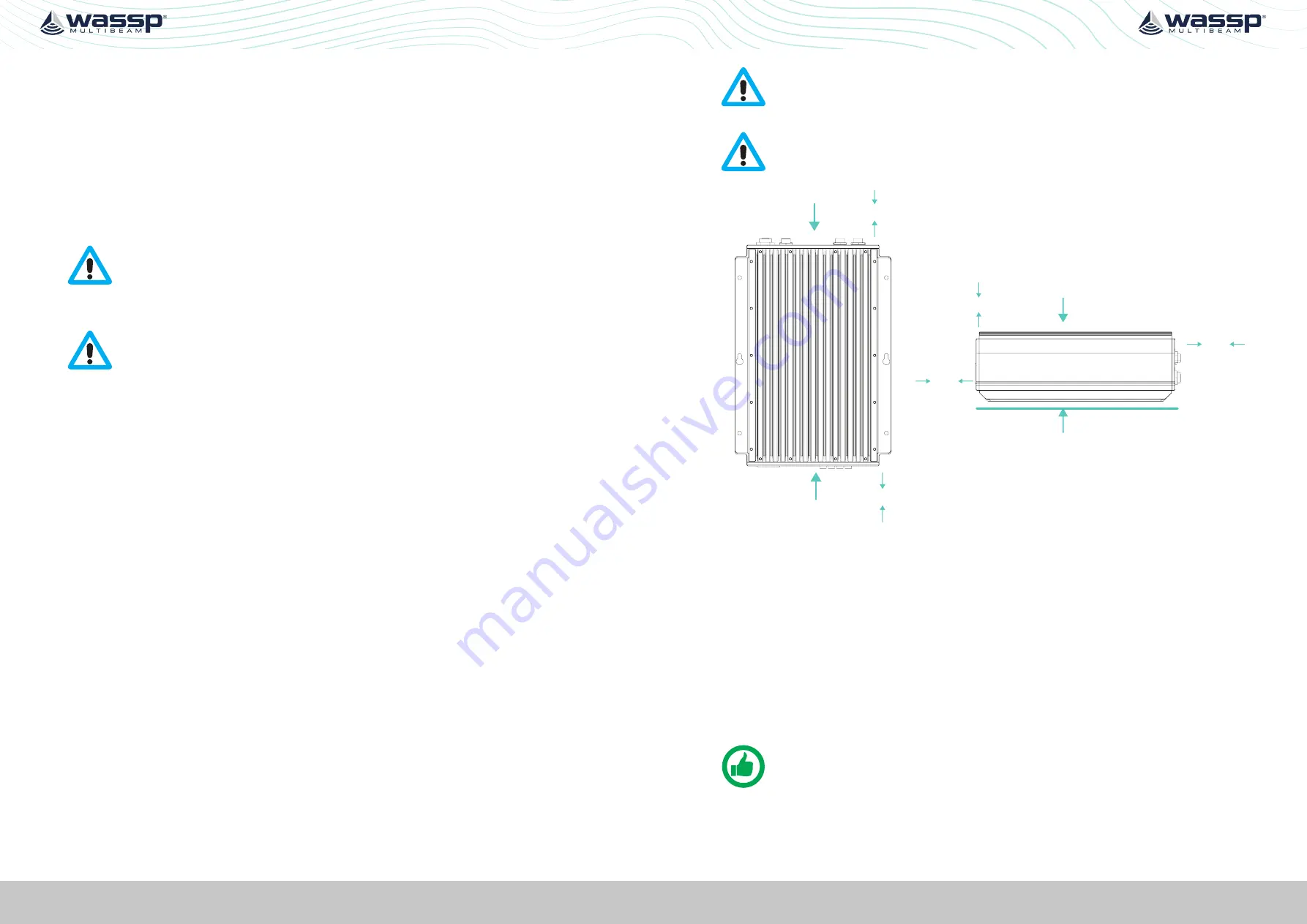
CAUTION: IF DRX is mounted in an enclosed space forced ventilation as
described below is required.
Back Plate
Front Plate
300mm
clearance
500mm
clearance
Top
Hard Surface
300mm
clearance
300mm
clearance
500mm
clearance
Figure 4. DRX Bulkhead Mount
Figure 5. DRX Horizontal Mount
Figures 4 and 5 show clearance required for cabling and forced air ventilation if DRX is in
an enclosed space.
Before installing the DRX in an enclosed space ensure that the ventilation is sufficient to
prevent overheating. Consider the following:
»
Cool air supply needs to be able to adequately dissipate the thermal output of DRX.
»
Ensure the hot exhaust air from the enclosed area does not recirculate into the DRX.
Perforations in the top will assist in removing exhaust air.
»
Install the DRX in a position to allow the air flow to circulate effectively through the
outlet.
»
Route all cabling to minimise blockage of airflow.
NOTE: If operating in a high ambient environment forced airflow over the DRX
will significantly improve thermal performance. Always make sure that there is
adequate ventilation.


