


Page 18 of 102
Page 19 of 102
Doc: DRX Installation
Version: 7.1 January 2021
Doc: DRX Installation
Version: 7.1 January 2021
DRX INSTALLATION MANUAL
DRX INSTALLATION MANUAL
3.5. CONNECTING THE DRX
This section describes the installation requirements for cables from and to the DRX.
Access to, and connection of all cables should be performed by a qualified installer.
3.5.1. Power Supply
The DRX should use a clean power supply. For best performance use a DC battery supply
or as a secondary alternative it is recommended to use a low noise converter.
CAUTION: A noisy power supply will have direct impact on system
performance.
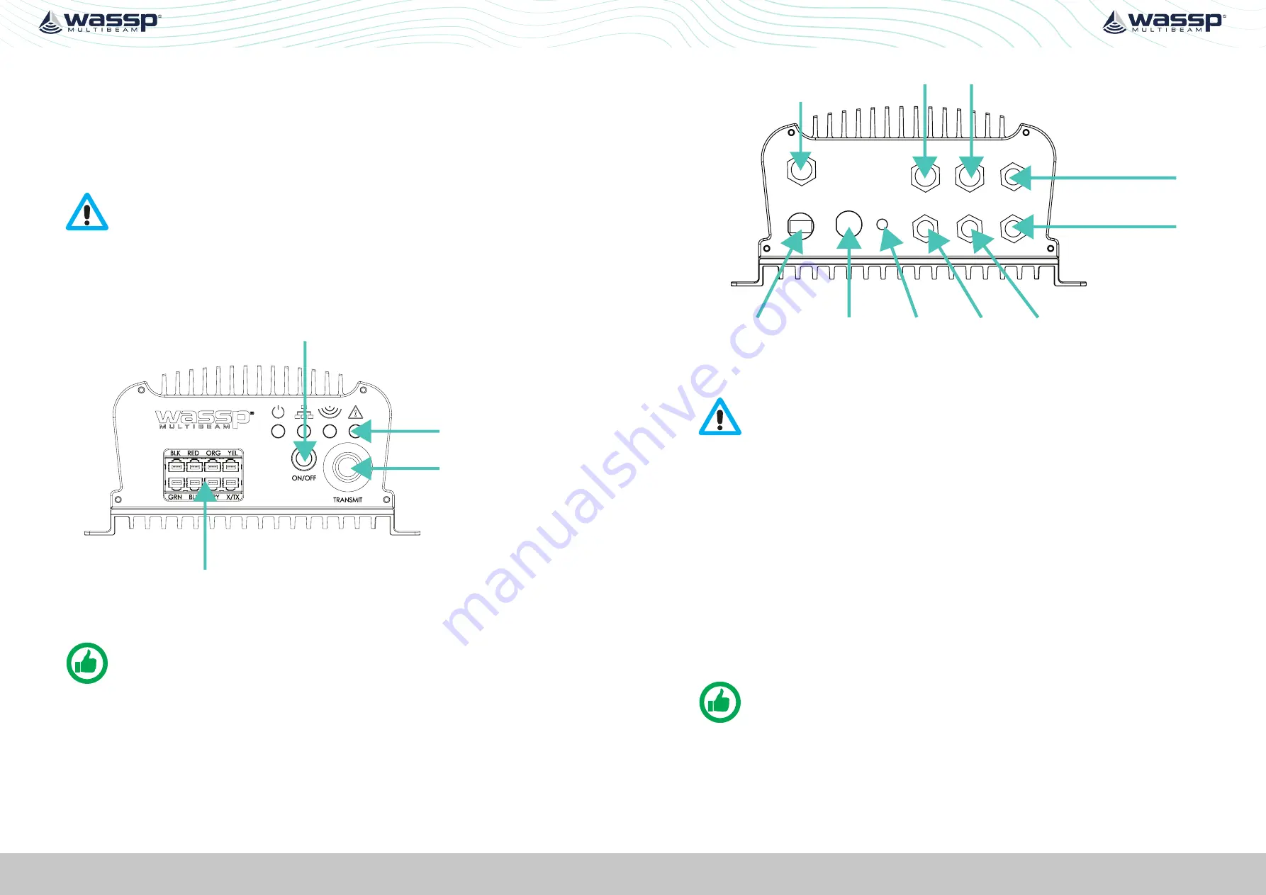
3.5.2. Connectors and Components
This section identifies the various connectors exposed on the DRX.
Transducer TX
Transducer RX
Power On / Off
LED Indicators
Figure 6. Front Plate
NOTE: X/Tx connector in Transducer RX block is only used for IP67 version of
DRX.
For descriptions,
see “3.5.3.1. Cables and Components – Front Plate” on page 19.
Grounding
Point
Power
Ethernet
N2K
Serial RS-232
RS-422-A
FAN
(DRX-46 only)
RS-422-B
AUX
NMEA 0183
AUX
N2K
POWER
LAN
FAN
0183
RS232
RS422-A RS422-B
Figure 7. Back Plate
CAUTION: All serial cables from sensors on RS-232, RS-422 or NMEA 0183
should be direct with no splitters or interface boxes, unless supplied by
WASSP. Failure to do this will result in compromised mapping performance
due to potential timing issues.
For descriptions,
see “3.5.3.2. Connectors and Components – Back Plate” on page 21.
3.5.3. Cables and Components
3.5.3.1. Cables and Components – Front Plate
Power On/Off
The power button controls system on/off through soft control. It requires power to be
connected to the unit.
»
Short press the power button to turn the power on. To power down, press and hold
the power button for 4 seconds (to prevent bumping starting a power down).
»
Power on/off can also be controlled remotely using the remote control cable on
back plate, referenced in the following page.
NOTE: Remote Power Control is described in


