


Page 40 of 102
Page 41 of 102
Doc: DRX Installation
Version: 7.1 January 2021
Doc: DRX Installation
Version: 7.1 January 2021
DRX INSTALLATION MANUAL
DRX INSTALLATION MANUAL
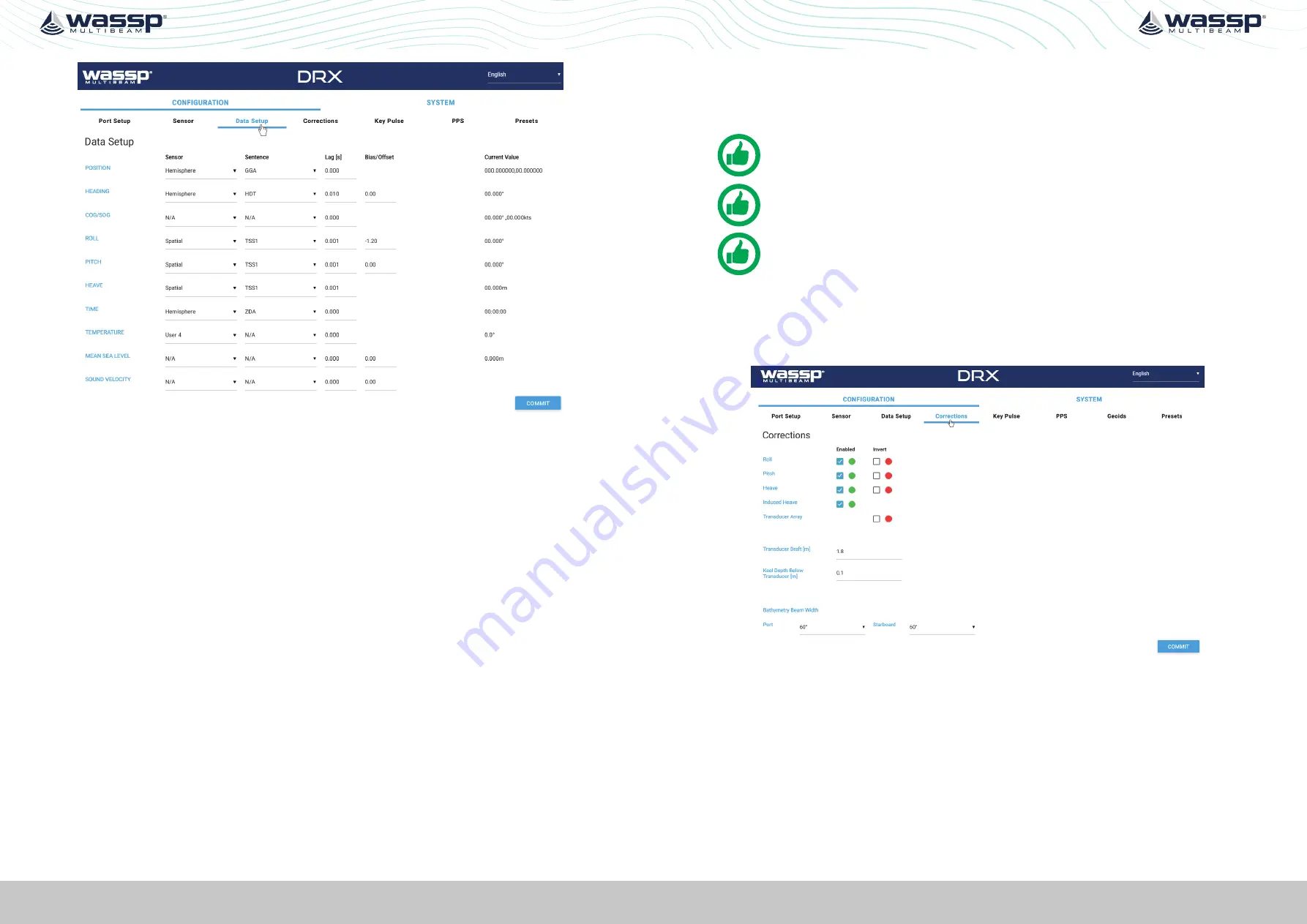
Figure 21. DRX Setup, Data Setup Tab
For each data type setup the following:
»
SENSOR
; The specific sensor that is supplying the data, selected from the drop
down. This sensor will have been configured under the
SENSOR
tab.
»
SENTENCE
; Select the appropriate sentence from the drop down. This can be cross-
referenced with the data being monitored under the
PORT SETUP
tab to make sure
that it is available to the DRX.
»
LAG
; The sentence lag (also called latency or delay) from the specified sensor
should be entered here.
Section “5.3. Commissioning Step 3: On Water Patch Tests”
gives detail on calculating delay for GPS position. Lag for attitude
data should be obtained from the sensor manufacturer specification.
»
BIAS
; The bias (also called offset or correction) of a data type should be entered
here.
“5.3. Commissioning Step 3: On Water Patch Tests” on page 50
gives details
on calculating bias for each of roll, pitch and heading.
Data Types that are required to be setup include:
»
POSITION
and
HEADING
; Required for georeferencing the vessel for bathymetry
mapping.
»
ROLL PITCH
and
HEAVE
; Required for compensating for vessel motion
»
TIME
; Required for UTC time synchronisation and specifically for PPS accurate time
synchronisation.
Other data types that can be setup include:
»
WATER TEMPERATURE
; Used to calculate sound velocity which is required for
multibeam operation
»
SOUND VELOCITY
; Direct input of sound velocity allows for accurate compensation
for multibeam operation
»
MEAN SEA LEVEL
; Required if RTK Tides feature License is being used for
compensating for sea level using GPS height.
See “5.2.8. Geoids Tab” on page 48.
»
COG/SOG
; Allows for COG and SOG display the client application.
NOTE: ‘Current Value’ will display the values being used by the DRX. However
these will be raw values and not account for latency settings.
NOTE: Lag is in seconds and Bias is in degrees. Lag should be entered to
nearest millisecond and Bias to nearest 0.01 degrees.
NOTE: You must COMMIT or these settings will be lost.
5.2.5. Corrections Tab
The
CORRECTIONS
tab is used to enable or disable specific attitude corrections being
applied, to invert attitude corrections, to correct for depth through adjusting transducer
draft and to adjust swath width.
Figure 22. DRX Setup, Corrections Tab
By default, all attitude corrections should be applied for optimal performance. To enable
or disable specific attitude corrections:
1. Select the check boxes of the attitude correction that should be applied, under
ENABLED
.
2. Press
COMMIT
button to save any changes.
3. The indicator beside the check box shows the status of the DRX. If the indicator is
green the correction is enabled in the DRX. If the indicator is red the correction is
disabled in the DRX.
Attitude corrections may need to be inverted if either the sensor is mounted incorrectly
or if the sensor supplies inverted roll data, for instance:


