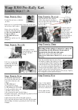
Wasp R500 Pro Owner'S Manual Download Page 7

STEP TWELVE 

STEP FIFTEEN 

STEP FOURTEEN 

STEP ELEVEN 

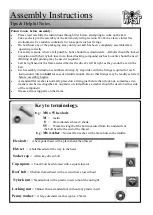
Assembly Instructions 

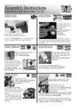
Assembling rolling chassis (Steps 1 to 15) 

STEP THIRTEEN 


Tap the key into the wheel hubs, centralize axle, & tighten 
the hub clamping soc cap.  

(N.B. The key should not be too tight that it is unable to be 
tapped into position & also should not be too loose that it is 
a sloppy fit. If the key is too tight it may be lightly dressed 
with a file, if it is too loose it can be centre punched from the 
top & if necessary dressed back with a file to produce a tap 
fit.). 

 
On either end of the axle place the external contracting 

30mm circlips 

in the grooves provided. 

 
When you are happy that the axle is centralized, small 
 indents aprox 2mm to 3mm should be drilled in the axle 
through the bearing grub screw holes & the grub screws  
refitted  
 
N.B. Take care not to damage the threads when drilling or lose 
the grub screws. 

(Remove any swarf). 

These, once fitted, will 

prevent the axle moving sideways under heavy side loads. If a 
small recess is not made & the screws are fitted, the surface of 
the axle will be damaged making it difficult to remove the 
bearings.  
 
Mount the rear wheels to the hubs with the tapered end of the 
nuts against the wheel & the valves facing outwards. 


Insert the 

6mm key 

into the 

sprocket carrier, adjusting the 
fit as before. It is good practice 
to clamp to the axle firmly 
first then tighten , the six 
sprocket fixings.  


The whole assembly may now be un-clamped, the alignment 
adjusted , the key checked & then re-clamped. 


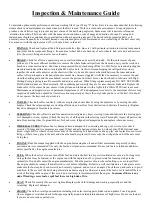
Insert the 6mm key into the brake 
carrier, adjusting the fit as before, 
& clamp the disc centrally. It is 
good practice to clamp the carrier 
to the axle firmly first, then tight-
en the six disc fixings. 


The whole disc assembly may now be un-clamped, the 
alignment adjusted, the key checked & then re-clamped. 

Mount the brake calliper over the disc,  

2x M8 x 20 soc cap & 2x M8 washers.  

Run hydraulic tube around the recoil 
side of the engine, secure the tube away 
from the engine with tie wraps.  


Mount the master cylinder to the  
inboard side of the bracket behind the 
seat. The hydraulic tube underneath 
facing the rear, actuating arm pointing 
up to the rear. 

2x M8 x 20 soc caps.  

2 x M8 washers. 

Fit the brake rod with 

1 x M6 lock nut 

either end followed by 

clevis, pins & clips. Secure assembly to the pedal &  brake 
cylinder arm. 

Please refer now to the following mechanical brake fitting 

instructions.  

Summary of Contents for R500 Pro

Page 1: ...mance Low ground pressure knobbly tyres reduces damage to the countryside while putting down the power Race proven hydraulic disc braking for instant stopping power Low noise Honda 4 stroke engines providing the punch using as little as 1 litre per hour of unleaded REDWOOD ENGINEERING UK LTD Wasp R500 Pro Rally Kart Owners Manual Assembly Maintenance Manual Phone 0044 0 1253 713266 Fax 0044 0 1253...

Page 2: ...o Rally Kart is not designed for highway use Protective clothing approved safety helmet eye protection must be worn at all times The Kart must never be operated without supervision or in conditions that may cause danger or damage to people or property Both the driver supervisor must have read the owners manual safety precautions before operating the Kart It is a condition of purchase that Redwood ...

Page 3: ... to be less than 30mph DO NOT OPERATE THE KART WITH LONG HAIR LOOSE CLOTHING SCARVES ETC The driver must fit the kart properly within the protection of the frame must be able to operate the controls fully without hindrance The driver should be fitted properly within the seat harness the wrist retainer straps must be used whilst the kart is in operation It is good practice whilst operating off road...

Page 4: ...n the assembly of the kart slowly with precision Work in a clean clutter free environment Use suitable containers for loose parts such as fixings Do not throw any of the packaging away until your kart has been completely assembled is operating correctly For safety reasons where at all possible bolts should face downwards All bolts should be locked in position with their nylock insert or a thread l...

Page 5: ...m M10 nylock nut Mount the opposite ends of the track rods to the underside of the stub axle arms using M10 x 40 hex bolt stub arm 2 x M10 x 20 heavy washers rod end M10 nylock Grease fit steering column with the solid nylon steering bush 1 x 3 4 washer split pin Mount the attached steering column bush in between the two rear facing brackets on the front axle beam with the column actuating arm fac...

Page 6: ...M5 washers 6 x M5 nylocks Keep the screw heads on the carrier side nuts washers on the sprocket side N B The sprocket must sit true on the machined register Location shoulder Leave fixings finger tight STEP NINE a Assemble rear axle as follows 1 Slide down lst wheel hub studs first 2 1st axle bearing with plates on loosen grub screw protruding grub screw boss first 3 Sprocket assembly sprocket sid...

Page 7: ...lt to remove the bearings Mount the rear wheels to the hubs with the tapered end of the nuts against the wheel the valves facing outwards Insert the 6mm key into the sprocket carrier adjusting the fit as before It is good practice to clamp to the axle firmly first then tighten the six sprocket fixings The whole assembly may now be un clamped the alignment adjusted the key checked then re clamped I...

Page 8: ... bracket This ensures free movement of the brake operating arm on that side that the M6 screw locknut do not foul the kart bracket Spacers are not normally required on Wasp F series karts Fit the M8 x 20 soc cap screws 2x washers lightly tighten ensuring the disc is roughly centred between the pads At this stage determine if the pads are parallel square to the disc A small degree of non alignment ...

Page 9: ... torque converter The torque converter has a pulley on the engine a pulley on the idle shaft These pulleys are asymmetrical have an almost flat pulley working face on the side nearest the engine This can be lined up in the same way as sprockets checking for parallel that they are in line The straight edge will form a small angle with the pulley This must be equal on both sides of the pulley face t...

Page 10: ... the risers are mounted to the chassis sliders the idle shaft assembly can be introduced into the bearings Step Four When aligned the idle shaft bearing bosses need to be secured to the idle shaft This is done by using a drill bit just smaller than the grub screw hole in the bearing drilling through the hole into the shaft by 1 2mm Be sure the shaft is centralized in the bearings make sure the ris...

Page 11: ...g 1x black heavy gauge washer 2 or 2x 3 8 x 11 4 mudguard washers 1x 5 16 spring washer 1x 5 16UNF x 11 2 hex bolt Torque down to 20ft Lbs Max Be sure the washers do not bend out through over tightening Warning The standard Honda engine has an imperial output shaft UNF threads Not metric in the output shaft its four planet holes The UNF thread form is fin er than on metric bolts Fit tension align ...

Page 12: ...o allow easy removal re fitting Mount the inspection panel using 6x self tapping screws 6x 5mm shake proof washers Step Twenty Mount the small inspection panel R H S of the engine using 4x 3mm equally spaced holes Fit the inspection panel using 4x self tapping screws 4x shake proof washers Warning Never run the engine with the guard or inspection sides removed Wasp R500 Pro Rally Kart Having now f...

Page 13: ...rough the long cable adjuster through the twin screw brass nipple through the pe dal loop back through the nipple Adjust up the play in the cable with the throttle closed Minor adjustment may be made with the cable adjuster Tighten the two nipple screws adjuster lock nuts Step Twenty Five Using r clips supplied the dual peddles can be fitted quickly and easily to suit the size of the driver Always...

Page 14: ...ute the wire to allow for movement of the steering wheel 4 The long wire goes from the switch tag to the existing stop on the engine 5 At the engine pull apart the bullet connection Black wire at the front of the engine joining in the long wire into the bullet then close the bullet securely insulate the connection This stop switch can now be used in conjunction with the existing engine switch Chec...

Page 15: ...ess webbing should be tie wrapped neatly securely to itself under no circumstances allowed to dangle loose Thread the two bungy lengths through the top of the bottom netting skirt and through the bottom edge of the roll bar net Secure each end around on itself wrapping around the roll bar upright Wasp R500 Pro Rally Kart On completion of your kart it is highly recommended that the driver kart supe...

Page 16: ...te the kart seek expert advice CABLES Check all cables run freely with excess play taken out either by using the adjusters or by moving the cable nipples Check the return springs are working effectively and are free from obstruction Lubricate if necessary Replace frayed or damaged cables where necessary STEERING Check for effective and free operation Investigate any heavy steering clean and lubric...

Page 17: ...o remove this build up Petrol is not suitable When the parts are clean and degreased they can be inspected for wear and damage and replaced as necessary When assembling the unit all the moving faces Not the pulley belt faces or the belt should be lightly lubricated with the recommended greaseless dust retardant lubricant The chain should be cleaned and then re lubricated with a low fling chain spr...

Page 18: ...nd or the kart be put in the situation where there is any possibility of the kart rolling over The top speed of the kart should be appropriately governed to the terrain age and ability of the driver This is recommended to be less than 30MPH Suitable protective clothing such as Padded fire retardant overalls sturdy foot wear gloves and an approved helmet with eye protection Must be worn at all time...

Reviews: