


Wasp R500 Pro-Rally Kart.
Assembly Steps 17 - 28.
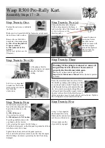
Step Twenty-Five.
Step Twenty-Six.
Fit the stop switch to the steering wheel with the tag beneath
the steering wheel. Two wires are supplied, one short, one
long. Strip back the wires at either end to provide a good,
electrical contact
1.
Crimp or solder the connections as shown in Diagram 1
.
(If using the shrouded connectors be sure of a good fit
with the wire to the connector & the connector with the
tag. Crimp as necessary.)
2.
The short wire goes from the switch earth to the earth on
the frame.
(Remove any paint to allow a good earth at
engine mount & the steering column top bush mount
).
3.
Route the wire to allow for movement of the steering
wheel.
4.
The long wire goes from the switch tag to the existing
stop on the engine.
5.
At the engine pull apart the bullet connection
(Black
wire at the front of the engine)
joining in the long wire
into the bullet & then close the bullet securely &
insulate the connection.
This stop switch can now be used in conjunction with the
existing engine switch. Check the switch operation is
satisfactory & the switch is off when the on/off plate
corresponds.
(ie. engine will stop when ‘Off’ , normally in the
downwards position.)
Check switch operation. Insulate all connections & secure the
wires to the frame & steering column.
The top speed of the kart should be
governed to suit the driver’s age & ability,
as well as the terrain. The maximum speed
for experienced drivers is recommended
to be less than 30mph.