


There should be a by-pass line around the consumption meter, which opens automatically in
case of excessive pressure drop.
If the consumption meter is provided with a prefilter, an alarm for high pressure difference
across the filter is recommended.
De-aeration tank, booster unit (1T08)
It shall be equipped with a low level alarm switch and a vent valve. The vent pipe should, if
possible, be led downwards, e.g. to the overflow tank. The tank must be insulated and equipped
with a heating coil. The volume of the tank should be at least 100 l.
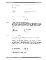
Circulation pump, booster unit (1P06)
The purpose of this pump is to circulate the fuel in the system and to maintain the required
pressure at the injection pumps, which is stated in the chapter Technical data. By circulating
the fuel in the system it also maintains correct viscosity, and keeps the piping and the injection
pumps at operating temperature.
When more than two engines are connected to the same feeder/booster unit, individual
circulation pumps (1P12) must be installed before each engine.
Design data:
Capacity:
6 x the total consumption of the connected engine
- without circulation pumps (1P12)
15% more than total capacity of all circulation pumps
- with circulation pumps (1P12)
1.6 MPa (16 bar)
Design pressure
1.0 MPa (10 bar)
Max. total pressure (safety valve)
150°C
Design temperature
500 cSt
Viscosity for dimensioning of electric motor
Heater, booster unit (1E02)
The heater must be able to maintain a fuel viscosity of 14 cSt at maximum fuel consumption,
with fuel of the specified grade and a given day tank temperature (required viscosity at injection
pumps stated in Technical data). When operating on high viscosity fuels, the fuel temperature
at the engine inlet may not exceed 135°C however.
The power of the heater is to be controlled by a viscosimeter. The set-point of the viscosimeter
shall be somewhat lower than the required viscosity at the injection pumps to compensate
for heat losses in the pipes. A thermostat should be fitted as a backup to the viscosity control.
To avoid cracking of the fuel the surface temperature in the heater must not be too high. The
heat transfer rate in relation to the surface area must not exceed 1.5 W/cm
2
.
The required heater capacity can be estimated with the following formula:
where:
heater capacity (kW)
P =
total fuel consumption at full 15% margin [l/h]
Q =
temperature rise in heater [°C]
Δ
T =
6-26
Wärtsilä 26 Product Guide - a9 - 7 September 2016
Wärtsilä 26 Product Guide
6. Fuel Oil System
Summary of Contents for WARTSILA 26
Page 1: ...W RTSIL 26 PRODUCT GUIDE...
Page 12: ...This page intentionally left blank...
Page 34: ...This page intentionally left blank...
Page 50: ...This page intentionally left blank...
Page 92: ...This page intentionally left blank...
Page 114: ...This page intentionally left blank...
Page 148: ...This page intentionally left blank...
Page 160: ...This page intentionally left blank...
Page 172: ...This page intentionally left blank...
Page 182: ...This page intentionally left blank...
Page 188: ...This page intentionally left blank...
Page 190: ...This page intentionally left blank...
Page 193: ......
Page 194: ......
Page 195: ......


