Fig 17-3
Shaft locking device and brake disc with calipers
17.4
Power-take-off from the free end
At the free end a shaft connection as a power take off can be provided. If required full output
can be taken from the PTO shaft.
The arrangement of the standard PTO shaft is shown in this section. The maximum allowable
bending moments on the PTO shaft depend on several criteria. As a guidance the values as
mentioned in table below can be used for the maximum allowed bending moments and radial
forces. When these values are exceeded, an extra support bearing is needed.
In the figures an indication is given how an extra support bearing could be arranged externally.
Such a support bearing is only possible when engine and support bearing are rigidly mounted
on the same base. This can be the ship’s foundation but this can also be a flexible mounted
common base frame.
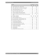
Table 17-1
Maximum allowable loading crankshaft flanges (can be applied
simultaneously) (9910ZT161e)
Axial Force
[kN]
Moments [kNm]
Radial Force
[kN]
V
L
10
9
13
100
Driving end
7
4.5
6.5
100
Free end
(PTO)
17-4
Wärtsilä 26 Product Guide - a9 - 7 September 2016
Wärtsilä 26 Product Guide
17. Power Transmission
Summary of Contents for WARTSILA 26
Page 1: ...W RTSIL 26 PRODUCT GUIDE...
Page 12: ...This page intentionally left blank...
Page 34: ...This page intentionally left blank...
Page 50: ...This page intentionally left blank...
Page 92: ...This page intentionally left blank...
Page 114: ...This page intentionally left blank...
Page 148: ...This page intentionally left blank...
Page 160: ...This page intentionally left blank...
Page 172: ...This page intentionally left blank...
Page 182: ...This page intentionally left blank...
Page 188: ...This page intentionally left blank...
Page 190: ...This page intentionally left blank...
Page 193: ......
Page 194: ......
Page 195: ......


