background image

94-0601-C

37

Start Up and Shut Down

Start Up

1.  Ensure that the RS24 Sensor is powered on.

2.  Double-click on the Dashboard icon.
     (or run the Dashboard application from
     

Start > All Programs > Guidance Marine Ltd > RS24 > RS24  

     Dashboard

).

3.  The Dashboard screen will appear. If the sensor was already   
     scanning, the radar image will be displayed straight away.

To Start the RS24 Dashboard

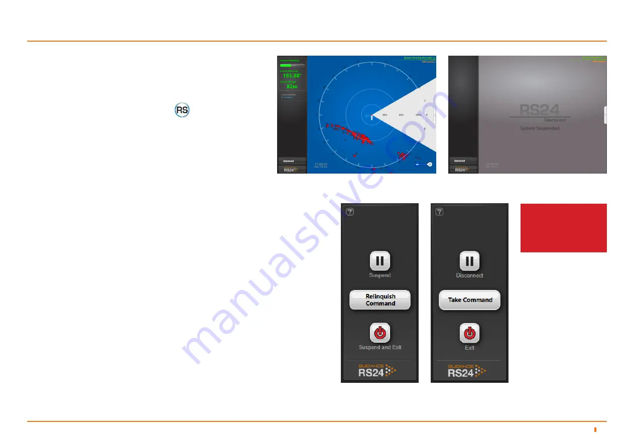
Click on the Guidance RS24 button in the lower left corner of the screen. The set 
of buttons revealed will depend on whether the Dashboard is In Command or in 
Monitoring mode. Each button is explained below.

•  Suspend

 - Places the sensor into a ‘sleep mode’ and the rotor ceases spinning. 

The Dashboard remains active and connected to the sensor ready to resume 
operations. This mode is suitable for use when travelling between locations.

•  Suspend and Exit

 - Places the sensor into the same ‘sleep mode’ as the suspend 

command (discussed above) and also closes the Dashboard.

•  Disconnect

 - Ceases communications between the computer running the 

Dashboard and the sensor but leaves the Dashboard open.

•  Exit

 - Closes down a Monitoring Dashboard without affecting the sensor.

Shut Down

To Suspend, Exit or Disconnect

Resume

To Resume a Suspend Sensor

Click on the 

Resume

 button on the Side Bar. The sensor begins to scan and the 

Dashboard displays the Bird’s Eye View.

Dashboard screen with sensor scanning

Dashboard screen with sensor suspended

In Command 

Dashboard

Monitoring 
Dashboard

See 

Multi-Dashboard 

RS24 Systems on page 
38

 for information on In 

Command/Monitoring 
functionality.

RS24 Dashboard Operation

5

5.1

Summary of Contents for RS24

Page 1: ...94 0601 C 1 RS24 W rtsil Guidance Marine Ltd 5 Tiber Way Meridian Business Park Leicester LE19 1QP UK T 44 116 229 2600 E sales wgm wartsila com USER S GUIDE www wartsila com guidance marine...

Page 2: ...re trademarks of their respective companies or organisations W rtsil Guidance Marine Ltd 5 Tiber Way Meridian Business Park Leicester LE19 1QP United Kingdom T 44 116 229 2600 UK Support 44 116 229 26...

Page 3: ...94 0601 A First release of RS24 User s Guide 28 03 2019 94 0601 B RS24 Product Label has been updated to the latest version 16 03 2020 94 0601 C Cable Routing Diagrams added and updated information to...

Page 4: ...vice Interface 23 22 4 1 Network Communication Settings 24 4 2 Radar Image Network Configuration 26 4 3 Vessel Definition 29 4 5 Blanking Zone 33 4 6 RS24 Dashboard Operation 5 Start Up and Shut Down...

Page 5: ...tant Safety Notes Non ionising Radiation Risk of Electric Shock Isolating the Sensor Lifting the Sensor Serial Numbers and Software Versions Product Labels Software Version Information To Display the...

Page 6: ...it It also explains how to upgrade the sensor software if required The Configuring the RS24 system on page 22 explains how to configure the system for your vessel The RS24 Dashboard Operation section...

Page 7: ...o the RS24 Dashboard and also to third party applications which support the ASTERIX CAT 240 open data format RS24 Dashboard Software The RS24 Dashboard software is the interface through which the oper...

Page 8: ...supply before making or breaking electrical connections or removing the radome cover CAUTION DOUBLE POLE NEUTRAL FUSING Isolating the Sensor It is recommended that a readily accessible disconnect dev...

Page 9: ...9 Production Release 10 04 2019 A1 C3 RS24 1169 Electrical Input parameters updates 03 10 2019 B ALL RS24 1239 Rebranding to Wartsila colours 03 12 2019 B01 C5 RS24 1316 Update CE number 09 03 2020 D...

Page 10: ...nsor Avoiding Other Sources of Radiation Sensor Dimensions 11 11 13 2 1 2 2 Mounting Template 14 2 3 Universal Mounting Bracket 15 2 4 RS24 Electrical Interface 16 2 5 Power Supply and Cable Specifica...

Page 11: ...c Mounting Guidelines The following guidelines apply to all vessel types and applications The sensor should be mounted Well above sea level to prevent swamping or immersion To allow for easy access to...

Page 12: ...2 1 For optimal operation the sensor field of view should be kept clear of obstructions excluding areas which will be covered by a blanking zone For a typical fore mast mounting position the sensor sh...

Page 13: ...94 0601 C 13 Sensor Dimensions Installing the Sensor Hardware and Software 2 500 368 5 312 5 56 120 NOT TO SCALE 2 2 RS24...

Page 14: ...that any custom made plinth is flat rigid and horizontal able to support 25kg and to receive four M8 mounting bolts 240 240 Edge of Radome Mounting Plate Four 9mm clearance holes to take M8 bolts 500...

Page 15: ...a handrail or other suitable railing Note Ensure that the railing is strong enough to support the combined weight of the sensor and bracket 30kg Universal Mounting Bracket Front View Universal Mountin...

Page 16: ...e Pin 2 Neutral Pin 3 N A PE Earth Ethernet Comms Connector Amphenol C016 30G006 200 12 6way Power Earth PE Connector Function CAT5 Cable Colour Pin 1 RX Orange White Pin 2 RX Orange Pin 3 N C Pin 4 N...

Page 17: ...and fitted by the installer to match the particular requirements for the vessel W rtsil Guidance Marine recommends that flexible multicore cables are used in all applications Cables should meet the re...

Page 18: ...If the display remains stuck on one screen the sensor should be restarted Under fault conditions the Sensor Information Display may show troubleshooting information Follow the instructions on the dis...

Page 19: ...is displayed 4 If the IP Address shown is not correct for your sensor amend it 5 Click on OK After a couple of minutes if the installation is successful the RS24 Installation Summary screen shows Ins...

Page 20: ...94 0601 C 20 3 Installing the RS24 Client Software Installing RS24 Client Software 21 3 1...

Page 21: ...ceInterfaceSetup exe files on the USB memory stick which was supplied 2 Double click on the RS24DashboardSetup exe file The Welcome screen is displayed 3 Click on the Install button The RS24 Dashboard...

Page 22: ...RS24 System Using the RS24 Service Interface 23 4 1 Network Communication Settings 24 4 2 Radar Image Network Configuration 26 4 3 Vessel Definition 29 4 5 Blanking Zone 33 4 6 Parameter Configuration...

Page 23: ...us of the system e g System Running Normally or System Suspended Activity Wheel A green rotating animation when the RSI is connected to the sensor green and stationary when disconnected red and statio...

Page 24: ...picks up the change when next opened To Modify the RS24 s Record of the Sensor s Network IP Address 1 Click on the Network Config tab of the RS24 Service Interface 2 Click on the Disconnect button if...

Page 25: ...3 Click on the Edit button in the Sensor On Board Network Configuration section 4 Amend the Sensor Address as required 5 Click on Apply to save the changes Communications between the RS24 Service Inte...

Page 26: ...essel network setup and raw radar images are not required then the raw radar image channel can be disabled ASTERIX Address This is the IP address of the receiving client The default setting is 0 0 0 0...

Page 27: ...oint connection from the RS24 to a single computer running the RS24 dashboard The RS24 is capable of almost filling the bandwidth of a 100 Mbit connection If it is being connected into a network with...

Page 28: ...ty radar processing To allow the RS24 Sensor to generate radar images when an RS24 Dashboard is not connected you should disable the Auto Suspend feature When Auto Suspend is disabled the RS24 Sensor...

Page 29: ...allel to the vessel s centre line running from bow to stern If the sensor is at a slight angle to the centre line enter a Bearing Offset to compensate for this See Bearing Offset on page 31 to find th...

Page 30: ...ntinued Bow and Starboard Offsets Enter the correct Bow and Starboard Offset values on the Vessel tab See Vessel Definition on page 29 Bow Offset Starboard Offset RS24 Sensor PORT SIDE STARBOARD SIDE...

Page 31: ...rt Sensor perpendicular to vessel centre line Bearing Offset 270o Sensor Facing Starboard Connection panel facing starboard Sensor perpendicular to vessel centre line Bearing Offset 90o Sensor Facing...

Page 32: ...tton To Import Vessel Definition from a File 1 Click on the Take Command button if the RSI is not already in command mode 2 On the Vessel tab click on the Import button 3 Locate the required XML file...

Page 33: ...e circle to the nearest degree Generally once the Blanking Zone has been set it will not need to be changed To Define a Blanking Zone 1 Click on the Take Command button if the RSI is not already In Co...

Page 34: ...This is in addition to the RS24 Service Interface itself It displays the command mode and name of each connected computer client The Alarms Tab This lists each sensor based alarm event that has occur...

Page 35: ...contains version information for the RS24 Service Interface the Sensor software the serial number of the sensor contact details for W rtsil Guidance Marine Ltd and a button for opening an on screen c...

Page 36: ...creen and Bird s Eye View 41 Side Bar 42 Hotkey Buttons 44 Menu Pane 45 Vessel Orientation 46 To Modify the Radar Image 49 Dashboard Modes 38 5 2 Dashboard In Command Mode 38 Dashboard Monitoring Mode...

Page 37: ...and connected to the sensor ready to resume operations This mode is suitable for use when travelling between locations Suspend and Exit Places the sensor into the same sleep mode as the suspend comman...

Page 38: ...age will appear on the screens of the Monitoring Dashboards indicating that the system is suspended In this state clicking the Resume button on any Monitoring Dashboard will automatically put that Das...

Page 39: ...ashboard itself will be active but those relating to the Sensor will be disabled A Monitoring Dashboard displays the same radar image as the In Command Dashboard To switch a Dashboard from In Command...

Page 40: ...1 C 40 Screen Layout The Dashboard screen is split into three distinct sections these are 1 Main Screen and Bird s Eye View BEV page 41 2 Menu Pane page 45 3 Side Bar page 43 5 3 RS24 Dashboard Operat...

Page 41: ...important for the vessel outline to be correctly scaled and positioned on the BEV Radar Image Objects in the vicinity of the vessel are rendered in a colour corresponding to their strength of radar re...

Page 42: ...left hand side of the control marked to zoom out of the BEV display and on the right hand side to zoom in Status Display This consists of two fields Primary The primary part of the status display is i...

Page 43: ...ta at Cursor Position Coordinate Data of Cursor Position Command Mode Guidance Button Advanced Menu Button Cursor Information The RS24 Dashboard will display the current cursor position s range and be...

Page 44: ...Toggles the shape of the BEV between circular and rectangular F9 Toggles between the day view and night view F10 Capture a screenshot of the Dashboard interface and save it to disk F11 Toggles full s...

Page 45: ...Bar is pressed This causes the Main Screen to contract towards the top of the screen Clicking the same button for a second time causes the Menu Pane to disappear and the Main Screen to be restored to...

Page 46: ...tting the Vessel Orientation one just for the current Dashboard session and the other which will apply to all Dashboards in the system and will persist after a Dashboard has been closed and re opened...

Page 47: ...htness control To change the day night mode and adjust brightness 1 Navigate to Advanced Display Options Display Settings 2 Click on one of the Day Night Mode symbols 3 Click on the left side of the S...

Page 48: ...the differentiation between weaker and stronger reflections allowing easier identification of bright targets in the scene A high gain setting reduces the differentiation between weaker and stronger r...

Page 49: ...rails Determines the extent to which recent movements and changes to the surroundings are represented in the radar image With the Trails slider at its minimum setting the image is an instantaneous sna...

Page 50: ...ck on the Hotkeys tab 2 Click on the Start Manual Data Logging button To start data logging There are many ways you can stop logging on the RS24 Dashboard you can either 1 Navigate to Advanced Data Lo...

Page 51: ...to update the list of USB drives and the Available Space value N B In addition to data logs screenshots from the selected time period a list of alarms and some trace files from the sensor are also ex...

Page 52: ...Keyboard 53 6 1 Low Temperature Set Up 55 6 3 Regular Maintenance 56 6 4 Working with Alarms 54 6 2 Filtering Alarms 54 Troubleshooting 57 6 5 Installation Checklist 60 6 8 Index 62 6 9 System Specif...

Page 53: ...screen the OSK will already be enabled Otherwise click F12 or the Enable On Screen Keyboard button in the Dashboard Hotkeys menu To use the On Screen Keyboard Simply click on any text entry field and...

Page 54: ...he filter is activated and causes information messages to be hidden Click on the Alarm Filter button to toggle between activated and de activated Click on the Filter Selection button to choose which t...

Page 55: ...tart Up The RS24 Sensor will operate at temperatures ranging from 25 to 55 C When starting at very low temperatures the sensor may require up to 40 minutes to warm up sufficiently to start producing a...

Page 56: ...or are in place and well secured Ensure cables connecting to the RS24 Sensor are not pulled tight and have sufficient slack to maintain cable integrity Ensure all cables are routed correctly and safel...

Page 57: ...racteristic of radar itself As you move away from the other vessels these phantom structures will go away Sensor appears to have a blind spot in front behind it Due to its mounted location other aspec...

Page 58: ...ast Ethernet Sensor Power Power Cable P N 33 0121 3 40m Ethernet Cable P N 33 0124 3 40m 16A 5A 5A UPS RS24 Sensor Link Cable Ethernet Power RS24 Monitor Monitor Power Cable Monitor Cable RS24 Client...

Page 59: ...th Beam Width 1 4o 3dB width Elevation Beam Width 5o up and 40o down Azimuth Side Lobe Suppression System to two way Inside 10o 25dB Outside 10o 40dB Minimum Range 1m Maximum Range 1000m2 Target 1500m...

Page 60: ...sensor s serial number is shown correctly The sensor and Dashboard software version details are correct Dashboard Display Options The vessel orientation is set correctly If the Marine Processor does n...

Page 61: ...dar X band and S band Whilst the RS24 system is running switch on the vessel s X band and S band radar Ensure that the RS24 system does not suffer any radial interference streaks Ensure that the vesse...

Page 62: ...ring Alarms Full Screen Mode 54 44 G Gain 48 H Help 44 Exit Exporting Data Logs 36 51 Hotkeys 44 I In Command Installation 23 38 10 20 61 IP Address 24 K K Band 7 59 L Labels 9 M Main Screen 41 N Netw...

Page 63: ...lay 44 51 42 18 System Specifications Shutdown Side Bar 59 37 40 43 Software Version 9 Starboard Offset 29 30 Status Display Suspend Take Command 42 23 28 37 23 38 Trails Troubleshooting Upgrading Sen...

Page 64: ......

Reviews: