4.2.9
Camshaft and valve mechanism
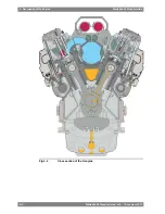
The camshaft is built of forged pieces with integrated cams, one section per cylinder. The
camshaft sections are connected through separate bearing journals, which makes it possible
to remove single camshaft sections sideways. The bearing housings are integrated in the
engine block casting and thus completely closed.
4.2.10
Camshaft drive
The camshaft is driven by the crankshaft through a gear train. The gear wheel on the crankshaft
is clamped between the crankshaft and the end piece with expansion bolts.
4.2.11
Fuel injection equipment
The low pressure fuel lines consist of drilled channels in cast parts that are firmly clamped to
the engine block. The entire fuel system is enclosed in a fully covered compartment for
maximum safety. All leakages from injection valves, pumps and pipes are collected in a closed
system. The pumps are completely sealed off from the camshaft compartment and provided
with drain for leakage oil.
The injection nozzles are cooled by lubricating oil.
Wärtsilä 46F engines are equipped with twin plunger pumps that enable control of the injection
timing. In addition to the timing control, the twin plunger solution also combines high mechanical
strength with cost efficient design.
One plunger controls the start of injection, i.e. the timing, while the other plunger controls
when the injection ends, thus the quantity of injected fuel. Timing is controlled according to
engine revolution speed and load level (also other options), while the quantity is controlled as
normally by the speed control.
4.2.12
Lubricating oil system
The engine is equipped with a dry oil sump.
In the standard configuration the engine is also equipped with an engine driven lubricating oil
pump, located in free end, and a lubricating oil module located in the opposite end to the
turbocharger. The lubricating oil module consists of an oil cooler with temperature control
valves and an automatic filter. A centrifugal filter on the engine serves as an indication filter.
The pre-lubricating oil pump is to be installed in the external system.
4.2.13
Cooling water system
The fresh water cooling system is divided into a high temperature (HT) and a low temperature
(LT) circuit. The HT-water cools cylinder liners, cylinder heads and the first stage of the charge
air cooler. The LT-water cools the second stage of the charge air cooler and the lubricating
oil.
In the most complete configuration the HT and LT cooling water pumps are both engine driven,
and the electrically actuated temperature control valves are built on the engine. When desired,
it is however possible to configure the engine without engine driven LT-pump, or even without
both cooling water pumps.
The temperature control valves are equipped with a hand wheel for emergency operation.
4.2.14
Turbocharging and charge air cooling
The SPEX (Single Pipe Exhaust) turbocharging system is designed to combine the good part
load performance of a pulse charging system with the simplicity and good high load efficiency
of a constant pressure system. In order to further enhance part load performance and prevent
excessive charge air pressure at high load, all engines are equipped with a wastegate on the
Wärtsilä 46F Product Guide - a19 - 1 December 2017
4-3
4. Description of the Engine
Wärtsilä 46F Product Guide
Summary of Contents for 12V46F
Page 1: ...PRODUCT GUIDE Wärtsilä 46F ...
Page 44: ...This page intentionally left blank ...
Page 52: ...This page intentionally left blank ...
Page 78: ...This page intentionally left blank ...
Page 102: ...This page intentionally left blank ...
Page 124: ...This page intentionally left blank ...
Page 144: ...This page intentionally left blank ...
Page 162: ...This page intentionally left blank ...
Page 186: ...This page intentionally left blank ...
Page 192: ...This page intentionally left blank ...
Page 194: ...This page intentionally left blank ...
Page 197: ......
Page 198: ......
Page 199: ......

