


5
MEDIA INSTALLATION
WARNING: Only use approved decorative media (glass, lava rock, ceramic
log sets, etc.) that have been manufactured for specific use in fire features.
WARNING: Media must be ½” or larger in size to prevent media from falling
into gas orifices and blocking flow of gas out of jets. Use approved media only.
WARNING: Burner and jets can be covered by 1/4” to ½” of media above
jets.
PLEASE NOTE - covering over jets more than 1/4” to
½
” may create
back pressure and gas leakage through air cross holes resulting in pooling
of gas under the fire feature which can result in explosion.
Also note that
flame pattern will be affected by any media coverage over gas orifice jets up
to and including smothering of flames.
WARNING: In rare cases, it is possible to create an unusual flame pattern
from media that could damage your enclosure. Enclosure damage from an
open flame fire feature is not covered under any warranty.
WARNING: When using electronic ignition systems please pay particular
attention to keeping media away from the pilot assembly area and/or away
from wind screen of pilot assembly. Incorrect media installation that blocks
pilot assembly will cause the pilot flame to suffocate, blocking of thermal
sensor and/or a delay in main burner ignition.
WARNING: The fire pit is designed to use approved media that is correctly
installed over the burner to achieve proper combustion. Use of any media
outside of the approved media sold by Warming Trends may void warranty
and effect proper operations.
Install enclosure and fire feature
per instructions provided by
manufacturer.
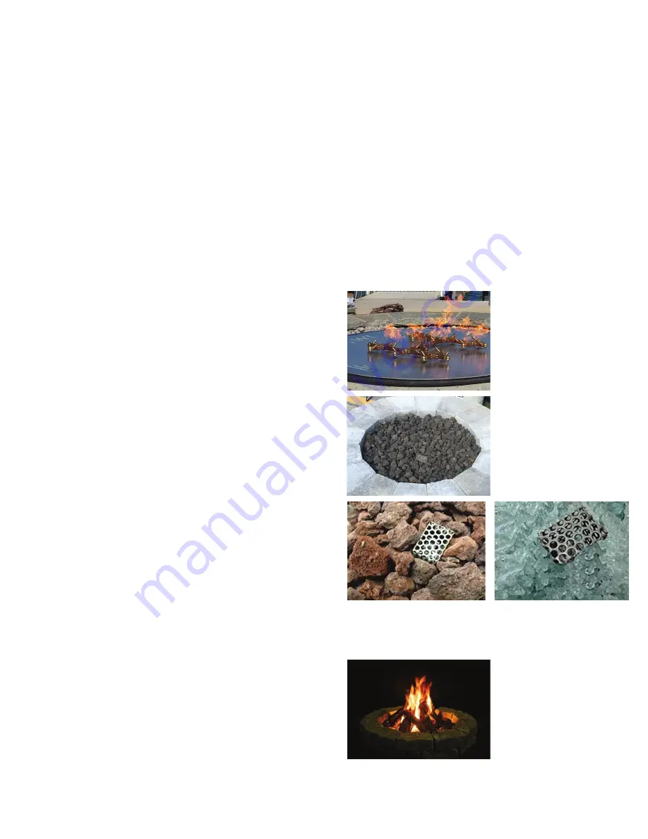
Apply media per instructions by
pouring media around burner
first, then pushing media towards
the gas jet orifices making sure
media does not fall into the gas
jet orifices. Check each gas jet
orifice prior to lighting to be sure
no media has fallen into gas jet
orifices.
For All Electronic Ignition Systems: Keep pilot assembly screen free
and clear of all media. Media should be piled no more than halfway
up screen only (not over full amount of screen) so that pilot gas orifice
opening is above media coverage allowing for pilot flame to easily reach
gas jet orifice.
For Ceramic Log Sets: Place logs
on top of lava rock base according
to preference and desired flame
pattern. For electronic ignition
systems - do not block, cover or
obstruct pilot assembly. Blocking,
covering or placing ceramic logs
too close to pilot may cause exces-
sive heat on pilot causing system
to fail. This is not covered under
warranty.
Gas or Liquid Propane. Do not use Natural Gas appliance with Liquid Pro-
pane or Liquid Propane appliance with Natural Gas. Refer to the labeling
on the appliance to confirm gas type.
WARNING: Fuel line sizing is the responsibility of the installer and must
be able to supply the stated maximum BTU listed for each product.
WARNING: Gas Plumbing Connections: Use only joint compound or
thread sealant or tape specific to gas use that is resistant to all gases. Apply
joint compound, thread sealant or tape to all male pipe fittings only and
DO NOT use on FLARED fittings. Be sure to tighten every joint securely.
WARNING: To prevent damage to burner, unhook fire feature from gas
supply during pressure leak tests of the fire feature.
WARNING: Before use, be sure to test all gas connections for leaks. Do
not use fire feature if there is evidence of leaking gas. If leak is suspected,
turn off main gas supply immediately and call a qualified gas technician
to repair.
WARNING: During Media Installation - when filling the pan with lava rock
and/or decorative glass and/or any covering material including log sets,
the instructions for Media must be followed.
WARNING: For electronic ignition systems, which have an extended
or detached valve box, the area in which the valve box is installed must
conform with all installation requirements, including but not limited to
location, construction, venting and local codes. Failure to do so may result
in personal injury, property damage or explosion.
WARNING: If using an LP bottle/tank, position bottle/tank at safe dis-
tance away from flame. Do not place LP bottle/tank inside the enclosure.
WARNING: Use only the key provided to turn the gas valve. Use only
hand strength to turn the gas key valve. Never use tools to turn the gas
valve. If key valve will not turn by hand, do not try to repair it. Contact a
qualified gas technician. Forcing or attempting to repair valve may cause
fire or explosion.
1. Verify correct gas type (gas supply should match burner type.)
2. Verify correct pressure.
3. Purge gas lines of air, water and debris.
4. Perform all leak test with leak detector or leak reactant on main
gas supply and repair leaks as necessary.
5. For 24V electronic ignition models have a qualified electrician
install proper power supply following all local codes.
6. Shut off Gas Supply and Power to fire-pit.
7. Inspect flex line for punctures or breaks in lines.
8. Connect fire-pit to main gas supply. Avoid sharp bends with flex
line to prevent whistling.
9. Position burner safely with access to all gas connections for testing.
10. Turn on gas supply and perform leak test on all connections and re-
pair as needed. See detailed connection guide for your specific model.
11. Light burner.
12. For electronic ignition models, apply proper power supply.
Electronic Ignition models can either be hard wired into main
power supply or plugged into NEMA Rated, above grade, out-
door specific, GFCI outlet/receptacle. Electrical can be used in
combination with on/off light switch (no dimmers) and/or remote
control receivers.
13. Once fire pit is lit, perform leak test on all gas connections.
Repair as needed.
14. Turn off fire pit and allow to cool.
15. Set burner into properly constructed enclosure.
16. Apply media as per installation instruction.
17. Complete final verification of correct operation and lighting.
18. Review safety manual with end user and instruct end user not to
change/ modify fire pit or media in any way.
19. Leave manual with end user.
WARRANTY REQUIREMENT:
Warranty is void if
valve box for any/all electronic ignition system is opened
or tampered with in any way. See warranty section for full
warranty requirements.


