30
The system corrosion inhibitor level must be checked (instant onsite test kits are available from
inhibitor manufacturers) and additional inhibitor must be added if the system is found to be
underdosed. Refer to the inhibitor manufacturer for further guidance.
Note: All product warranties will be invalidated if the appliance is not serviced at least
annually or as indicated by the user interface controller by a Warmflow or trained
technician and details recorded in the service record section of this manual.
4.2.2 Servicing the heat exchanger
Before commencing any servicing or maintenance ensure that the mains electrical supply to the
appliance is isolated. The mains electric isolator switch is located below the main electronics
box at the front of the appliance and should be locked by padlock in the off position (see Figure
1).
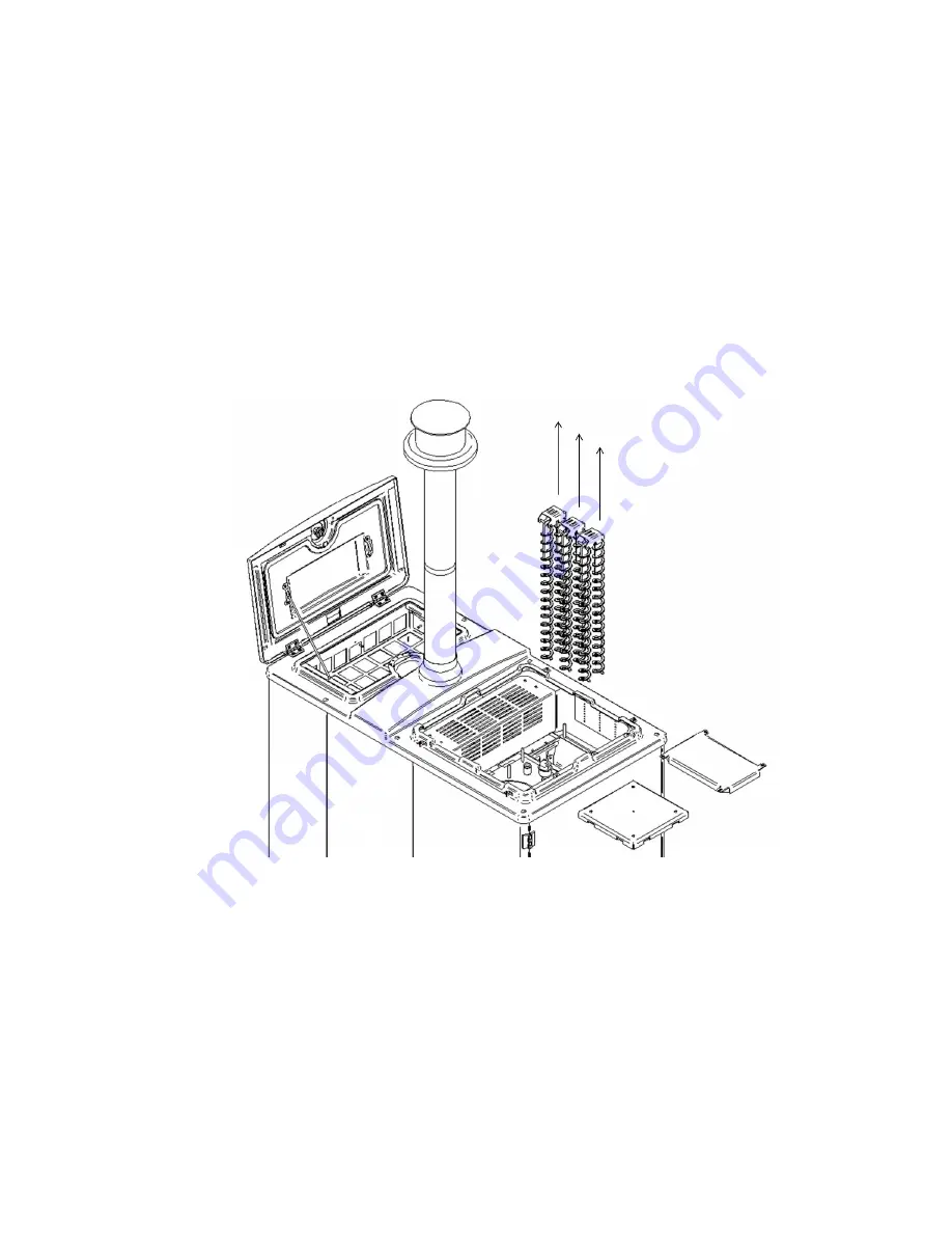
The top of the heat exchanger is accessed by removing the service lid and insulation.
The inspection door and cleaning mechanism door must then be removed to give access to the
heat exchanger and turbulators as shown in Figure 32.
The heat exchanger and air turbulators must be thoroughly cleaned to remove soot, fly ash,
carbon deposits and any other combustion residues.
The turbulators are mounted on a rocker shaft and can be withdrawn in pairs by lifting them
vertically from the heat exchanger tubes. The turbulators should be brushed with a steel brush
Figure 32: Turbulator Removal During Heat Exchanger Service.


