background image

14 


Operating Instructions 


Communicating with the patient 


 

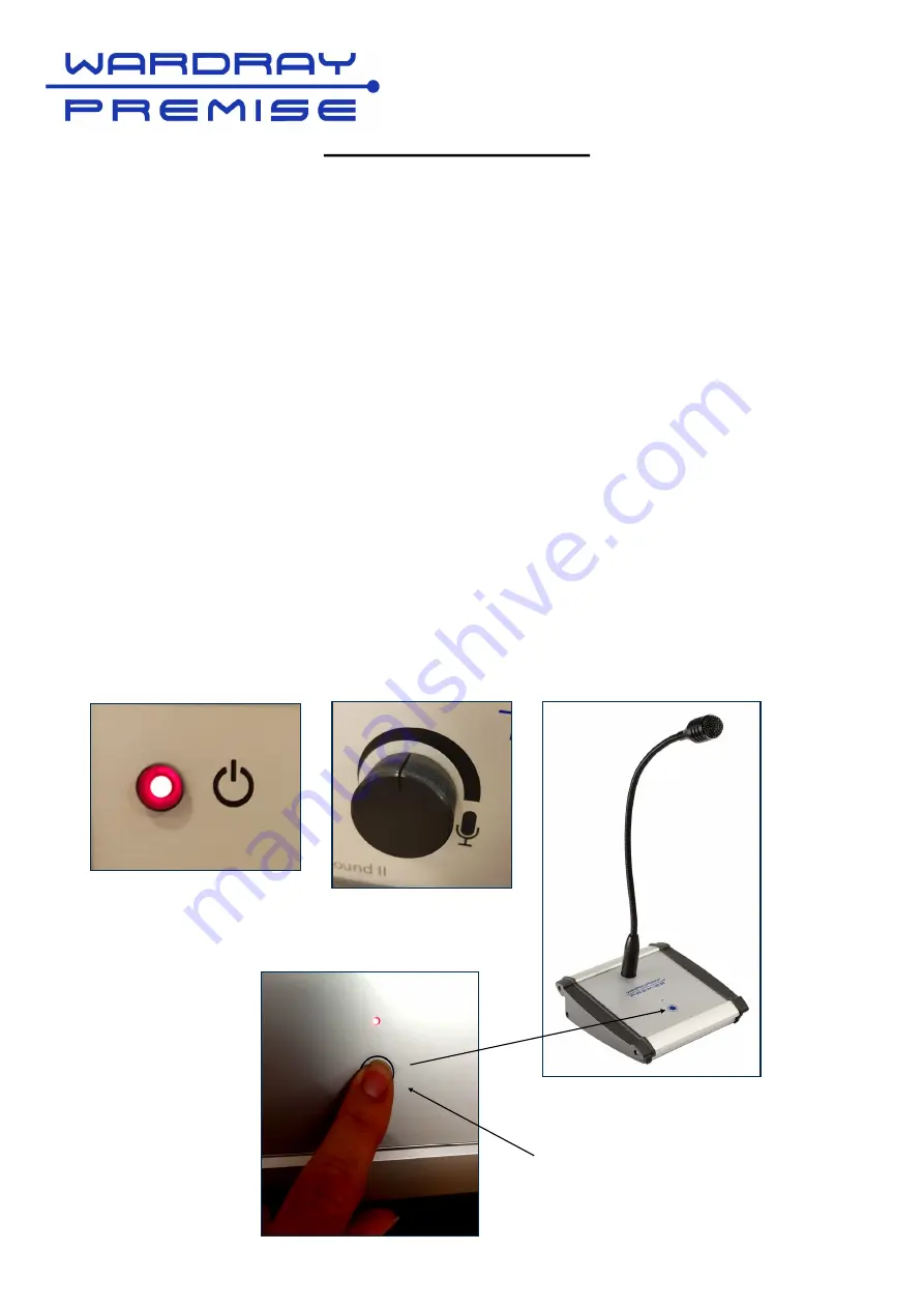
Ensure that the Pure Sound II is turned on (check the red LED on the front panel) Fig 1. 


 

Set the microphone volume dial to the mid-point (the dial cut out pointing vertically) Fig 2.  


 

To test the volume of the microphone output, press the button on the microphone unit, when 
the circuit is open to talk, an LED will light on the microphone base (Fig 3).  


 

Talk at a normal volume to the patient and confirm that the level of the transmission is 
acceptable. If not, adjust microphone volume up/down accordingly and retest. 


 

Care must be taken to check that the microphone is not ‘open’ (e.g. transmitting to the 
patient) when discussing anything that may be worrying, offensive or inappropriate. While the 
LED illumination is a guide, it is not recommended that this be taken as a definitive guide and 
that discretion is used at all times when a patient is being examined.  

Fig 1 

Fig 2 

Fig 3 

Summary of Contents for Pure Sound II

Page 1: ...March 2020 GEN S 20 266 MR200 Pure Sound II Audio Relaxation System OPERATORS MANUAL...

Page 2: ...0 3 3 2009 Mains Voltage flicker dmax 4 Product Complies with RoHS Directive 2011 65 EU To ensure that you obtain maximum benefit from your product please take a few minutes to read the enclosed infor...

Page 3: ...demonstrated safety in the MR environment within defined conditions including conditions for the static magnetic field the time varying gradient magnetic fields and the radiofrequency fields Suppleme...

Page 4: ...MR Conditional to 7T Stereo Acoustic Converter MR Conditional to 7T Important note Equipment should be set up in accordance with the layout diagram page 15 MR Unsafe items must not be taken into the M...

Page 5: ...udio Cable 4Core screened with plug to Stereo Acoustic converter 2 x Velcro Strips for securing Stereo Acoustic Convertor to Scanner if required 2 x Euro Plugs if required For MR Installations only MR...

Page 6: ...gned to receive audio media via the 3 5mm jack Fig 1 page 12 from a mobile phone or digital music device NB In order to use a mobile phone for the replay of audio media the phone must be set to a flig...

Page 7: ...ft Touch Microphone Rear of Audio Control Unit Power Socket Patient Headphone Output Audio Input Socket Audio Input from optional DVD Operator Microphone Input Socket Power Speaker Output On Off Power...

Page 8: ...room or control room Please note that powered speakers are NOT included supplied they need to be sourced locally The control unit has 7 connections on the rear panel Connection Icon Description Power...

Page 9: ...ncluded for use in operator room or waiting room Audio Input Socket 3 5mm 3 5mm audio input eg Mobile Phone or other audio To be used with the 3 5mm male to male extension lead supplied to allow easy...

Page 10: ...epress silver colour disc and push the airline into the opening Releasing the clip will secure the airline in place Repeat with the second airline Headphones and Earphones Recommended The disposable h...

Page 11: ...sent AND the power switch on the rear of the unit is turned on Operator Microphone Volume Dial Volume control for the microphone output Turning the dial clockwise will increase the volume anti clockwi...

Page 12: ...t to a mid point Once the patient is in place adjust the playback volume by using the Pure Sound II volume control ONLY Important Note The Patient playback via headphones is ONLY for the duration of t...

Page 13: ...13...

Page 14: ...ill light on the microphone base Fig 3 Talk at a normal volume to the patient and confirm that the level of the transmission is acceptable If not adjust microphone volume up down accordingly and retes...

Page 15: ...15...

Page 16: ...y following your local guidelines or instructions Please register your product with us via the Warranty Registration Form see page 22 for ease of contact in case of urgent upgrades or recalls If the u...

Page 17: ...TEREO ACOUSTIC CONVERTER Any attempt to open the unit parts will invalidate the warranty Any removal of covers or connections to the unit requires turning the unit OFF AND the complete removal of the...

Page 18: ...18...

Page 19: ...19...

Page 20: ...20...

Page 21: ...21...

Page 22: ...22...

Reviews: