5
Wanner Engineering, Inc.
United States
Instant Information: www.wannereng.com
(61) 33-5681 Fax (61) 33-6937
SCK-991-400B
Operation
Preparation For Operation
Caution: the following preparation must be done before the
pump is operated for the first time. Failure to follow these
instructions will result in serious damage to the pump.
Initial Lubrication
Note:
Oilers are set at the factory to their lowest position. This
setting places the oil level just below the center of the bottom
ball of the bearing when the housing is level. Higher levels may
cause churning and overheating of the bearings; lower levels
may not provide enough lubrication and may promote rapid
wear.
The correct oil level will be visible at the center of the
sign oil gauge.
Standard pumps are shipped with empty oil reservoirs.
Oil must
be added before operating the pump.
Attach the oiler to the
bearing housing, fill the bottle with oil, and place it in position.
Continue filling the bottle until it remains full of oil. Do not add
oil to the reservoir except through the oiler bottle.
Use a good grade of SAE 10W30 oil.
Keep the air vent clean to prevent pressure buildup caused by
normal heating that occurs in operation. A Trico Optomatic Oiler
No. EB-64 with a 4-oz capacity bottle is used.
The correct bottle
must be used with the corresponding oiler body.
Mechanical Seals
When mechanical seals are furnished with the pump, the
description and identification are indicated on the order writeups,
which are a part of the order acknowledgment, dimension print,
and packing list. The seals are installed and adjusted at the
factory. To properly prepare the seal for operation, various cooling
and flushing flows may have to be connected. Liquid from an
outside source may be required. Connect necessary cooling
and flushing flows to the seal, and be sure it is turned on before
starting the pump.
Important Precautions
Check the following items before starting the pump:
• Pump rotates freely by hand
Important: The motor rotation must be checked before
connecting the shaft coupling. Incorrect pump rotation
for even a short time will dislodge the impeller and
damage the impeller or casing, or both. The pump shaft
must turn clockwise when viewed from the motor end.
• Coupling is aligned
• Oiler is full and oil level is correct
• Suction valve is fully open
• Pump and suction line are full of fluid
• Water is supplied to stuffing box or gland flush
Priming
Vent all air from the suction line, and fill the line with liquid. Start
the pump with the discharge valve cracked open. After the
discharge pressure stabilizes, gradually open the discharge valve
to the required position. If flow is lost, close the discharge valve
and wait a few seconds for the discharge pressure to rebuild.
Continued flowing difficulty indicates an improper selection or
installation. Running the pump too long with improper prime
may destroy the sealing faces of the mechanical seal. It may
also cause mechanical damage from pulsation and interference
between rotating and stationary components.
Thermal shock may crack the ceramic stationary seat if the
temperature is raised from room temperature to 250°F in less
than 30 seconds.
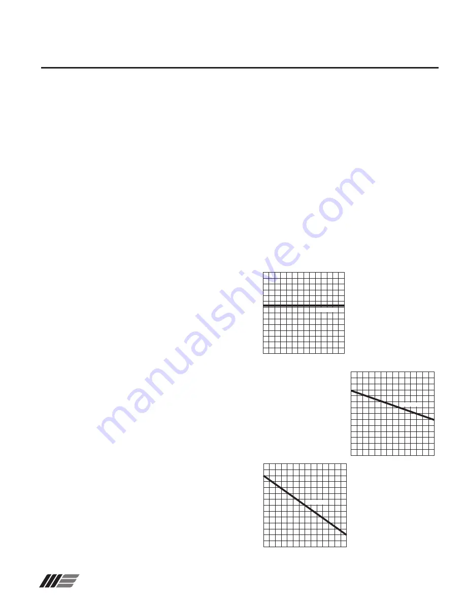
Maximum Operating Conditions
Note: These maximum operating conditions apply to pumps which
are exposed to room temperatures without external insulation.
Maximum operating temperature and pressure conditions are
shown in Fig. 5 below.
Notes:
• Maximum service temperature for all Kynar pumps: 250°F.
• For insulated pumps, multiply “Maximum Discharge Pressure”
by 0.8.
• Higher maximum discharge pressures are allowed for A50,
A60, or A70 pumps when pipe stress is removed from the
discharge flange. Contact the factory for details.
Temperature (F)
80
90
100
110
120
130
140
150
Maximum Discharge Pressure (PSI)
75
100 125 150 175 200 225 250
KYNAR 370
W0445
Temperature (F)
145
150
155
160
165
170
175
180
Maximum Discharge Pressure (PSI)
75
100 125 150 175 200 225 250
KYNAR 370
W0446
Temperature (F)
80
90
100
110
120
130
140
150
Maximum Discharge Pressure (PSI)
75
100 125 150 175 200 225 250
KYNAR 370
W0444
Fig. 5A:
Pump Size AA, AB
without insulation on
atmospheric side
Fig. 5B:
Pump Size A30, A40
without insulation on
atmospheric side
Fig. 5C:
Pump Size A50, A60,
A70 without insulation
on atmospheric side


