5.0 INSTALLATION AND FIXING
SILOTOP R03
2
FIL.100.--.M.EN Issue: A2
06.12
36
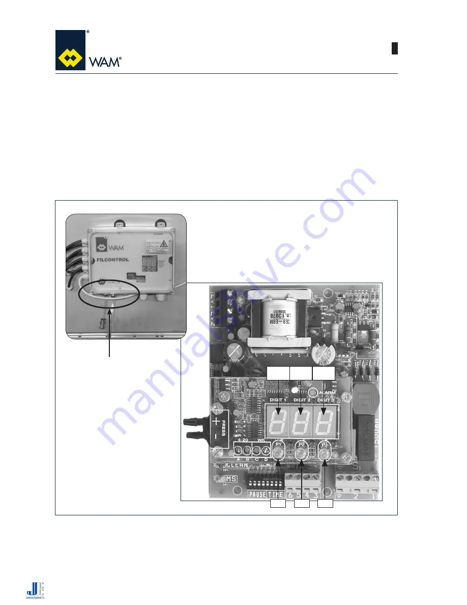
DIGIT 1 DIGIT 2 DIGIT 3
P1
P2
P3
a)
Make sure there is no air flow through the filter.
b)
Disconnect both hose pipes from the outside of the controller board casing (part A).
c)
Enter module settings mode of field 7 of the MDPE and set the value to 1.
d)
Save the value (
P3
+
P2
).
e)
Exit the module settings mode and read value XX in DIGIT2 and DIGIT3 on the display.
f)
Return to module settings mode and set field 7 to value XX.
g)
Save the value (
P3
+
P2
) and exit module settings mode (
P3
+
P1
).
h)
Reconnect the hose pipes to the controller board casing in the correct position (clean chamber tube of the
filter to the RH (-), foul air chamber tube of filter to the LH (+).
A
Jamieson Equipment Company | 5314 Palmero Court | Buford, GA 30518 | 800.875.0280 | [email protected]


